ELECTRICAL COMPONENTS (YUM1A/YUM2A)
8-57
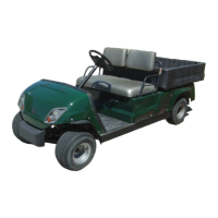
CHECKING THE REVERSE BUZZER
1. Check:
• Reverse buzzer
Does not sound → Replace.
a. Disconnect the reverse buzzer coupler
from the wire harness.
b. Connect the battery to the reverse buzzer
coupler as shown.
c. Check the buzzer sound.
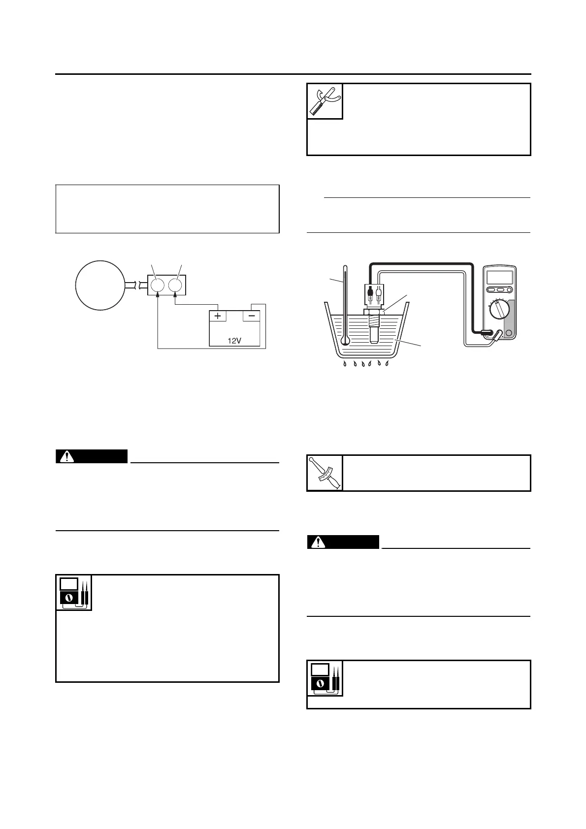
CHECKING THE ENGINE TEMPERATURE
SENSOR
1. Remove:
• Engine temperature sensor
• Handle the engine temperature sensor with
special care.
• Never subject the engine temperature sen-
sor to strong shocks. If the engine tempera-
ture sensor is dropped, replace it.
2. Check:
• Engine temperature sensor resistance
Out of specification → Replace.
a. Connect the digital circuit tester to the en-
gine temperature sensor terminals as
shown.
b. Immerse the engine temperature sensor
“1” in a container filled with water “2”.
Make sure the engine temperature sensor termi-
nals do not get wet.
c. Place a thermometer “3” in the water.
d. Heat the water or let it cool down to the
specified temperatures.
e. Measure the engine temperature sensor
resistance.
3. Install:
• Engine temperature sensor
CHECKING THE INTAKE AIR PRESSURE
SENSOR
• Handle the intake air pressure sensor with
special care.
• Never subject the intake air pressure sen-
sor to strong shocks. If the intake air pres-
sure sensor is dropped, replace it.
1. Check:
• Intake air pressure sensor output voltage
Out of specification → Replace.
a. Connect the test harness S– pressure
sensor 5S7 (3P) “1” between the intake air
pressure sensor and wire harness as
shown.
• Positive battery terminal →
pink “1”
• Negative battery terminal →
black “2”
Engine temperature sensor resis-
tance
2513–2777 Ω at 20 °C
(2513–2777 Ω at 68 °F)
Engine temperature sensor resis-
tance
210–221 Ω at 100 °C
(210–221 Ω at 212 °F)
Digital circuit tester (CD732)
90890-03243
Model 88 Multimeter with ta-
chometer
YU-A1927
Engine temperature sensor
16 N·m (1.6 kgf·m, 12 lb·ft)
Intake air pressure sensor output
voltage
3.51–3.77 V