VALVES AND VALVE SPRINGS
5-13
2. Replace:
• Valve guide
To ease valve guide removal and installation,
and to maintain the correct fit, heat the cylinder
head to 100 °C (212 °F) in an oven.
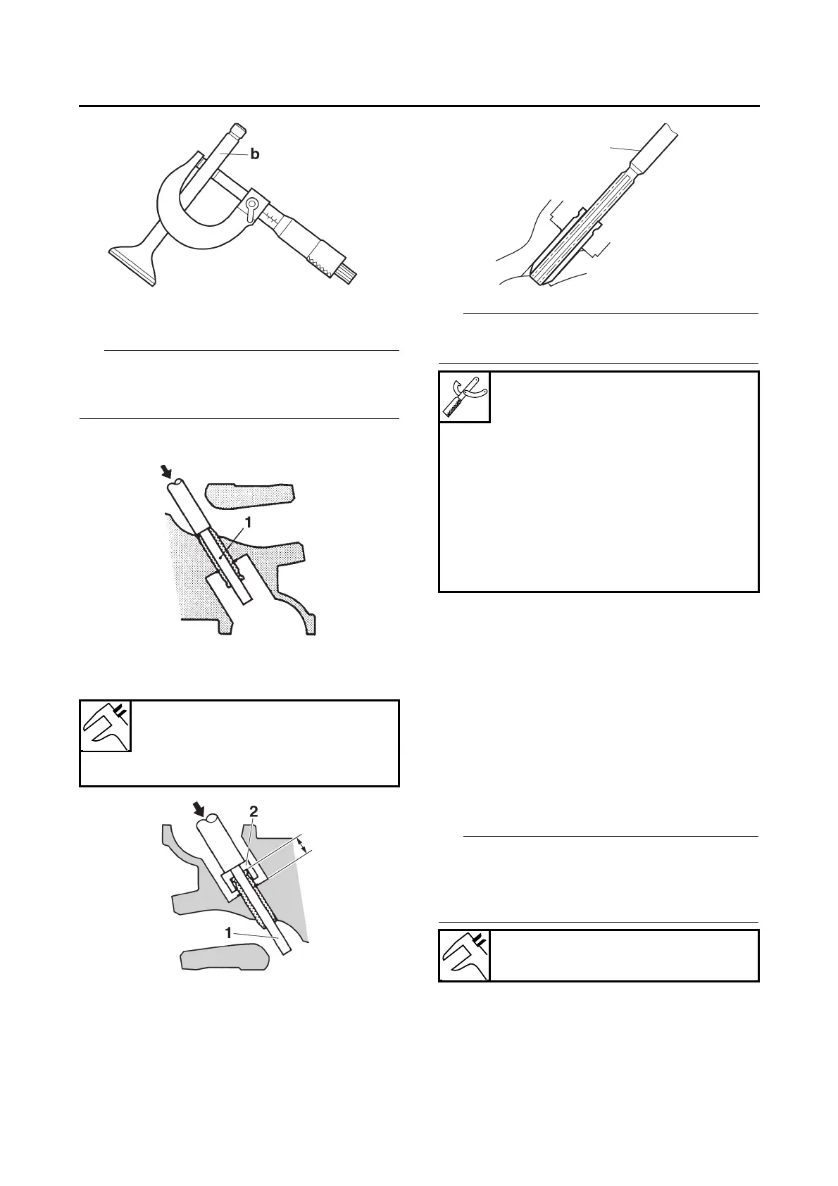
a. Remove the valve guide with the valve
guide remover “1”.
b. Install the new valve guide with the valve
guide installer “2” and valve guide remov-
er “1”.
c. After installing the valve guide, bore the
valve guide with the valve guide reamer
“3” to obtain the proper valve-stem-to-
valve-guide clearance.
After replacing the valve guide, reface the valve
seat.
3. Eliminate:
• Carbon deposits
(from the valve face and valve seat)
4. Check:
• Valve face
Pitting/wear → Grind the valve face.
• Valve stem end
Mushroom shape or diameter larger than the
body of the valve stem → Replace the valve.
5. Measure:
• Valve stem runout
Out of specification → Replace the valve.
• When installing a new valve, always replace
the valve guide.
• If the valve is removed or replaced, always re-
place the valve stem seal. (intake side only)
Valve guide position (intake)
9.6 mm (0.38 in)
Valve guide position (exhaust)
8.1 mm (0.32 in)
a. Valve guide position
a
Valve guide remover (ø6)
90890-04064
Valve guide remover (6.0 mm)
YM-04064-A
Valve guide installer (ø6)
90890-04065
Valve guide installer (6.0 mm)
YM-04065-A
Valve guide reamer (ø6)
90890-04066
Valve guide reamer (6.0 mm)
YM-04066
Valve stem runout
0.010 mm (0.0004 in)