2 - 23
SPEC
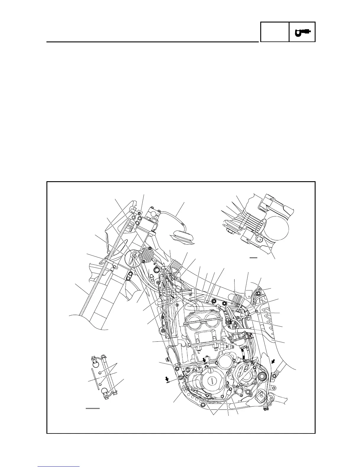
CABLE ROUTING DIAGRAM
EC240000
CABLE ROUTING DIAGRAM
1
Fuel tank breather hose
2
Clamp
3
Diode
4
Wire harness
5
Hot starter cable
6
Negative battery lead
7
Starter motor lead
8
TPS (throttle position sensor)
lead
9
Cylinder head breather hose
0
Neutral switch lead
A
Oil hose
B
AC magneto lead
C
Oil tank breather hose
D
Rectifier/regulator lead
E
Brake hose
F
Hose guide
G
Carburetor breather hose
H
Overflow hose
I
Coolant reservoir tank breather
hose
È
Insert the fuel tank breather
hose into the hole in the steer-
ing shaft cap.
É
Using a plastic locking tie, fas-
ten the diode of the wire har-
ness (at the white tape) and the
neutral switch coupler to the
frame, and cut off the tie end.
Ê
Fasten the wire harness, cool-
ant reservoir hose and hot
starter cable to the frame with a
plastic locking tie and cut off the
tie end.
Ë
Fasten the wire harness and
coolant reservoir hose to the
frame with a plastic locking tie
and cut off the tie end.
Ì
Fasten the wire harness to the
frame at its white tape with a
plastic locking tie and cut off the
tie end.
2
Ù
B
B
A
B-B
A
A
0
Ò
2
Ñ
2
B
Ó
C
Ô
D
E
F
Õ
Ö
2
×
2
F
1
È
2
É
3
2
Ê
4
5
2
Ë
2
Ì
2
Í
6
7
Î
2
Ï
8
9
0
A
2
Ð
Ø
G
G
H
I

 Loading...