t (2) Connector Specifications for SERVOMOTOR with Arrange the main circuit sequence to stop the
Brake SERVOMOTOR and fan motor when cooling fan alarm
occurs. (Alarm contact is ON at alarm occurrence).
• M, F*, D Series (Brake is provided to all types of D After alarm occurrence, make sure to stop the
series as standard.) SERVOMOTOR and fan motor within five minutes
A Phase U E since SERVOMOTOR self-cooling protection is set to
B Phase V F Brake terminal five minutes.
When cooling fan starts running, alarm detection
C Phase W G - signal turns ON for three seconds. Therefore, add a
D FrameGround -- - delay relay to the circuit for this time setting (three
Types without brake of 13 series do not use seconds).
E and F.
4.6.5 Impact Resistance.
*For USAFEM-02 and-03,
see connector on the right. When mounted horizontally and exposed to vertical
shock impulses, the motor can" withstand up to two im-
pacts with impact acceleration of 490m/s2(50G) (Fig.
• S Series 4.11).
(USASEM-02A).. NOTE
t A precision detector is mounted on the opposite-
Color of Lead Applicable Color of Lead Applicable drive end of AC SERVOMOTOR. Care should
Red Phase U Black .. be taken to protect the shaft from impacts that
Brake could damage the detector.
White Phase V Black
Blue PhaseW Green Frame Ground IVERTICAL
!
(USASEM-03A, -05A) (USASEM-08A to -30A) ' --_- IIIIL_=,ZONTAL
t O O Fig. 4.11 Impact ResistanceL I IUJ"V'"
4.6.6 Vibration Resistance
A PhaseU A PhaseU When mounted horizontally, the motor can withstand
B Phase V B Phase V vibration (vertical, lateral, axial) of 24.5m/s 2 (2.5G)
C Phase W - C Phase W (Fig. 4.12).
VERTICAL
Brake terminal Brake terminal
E E LAT . L
t F FLameground F Frameground
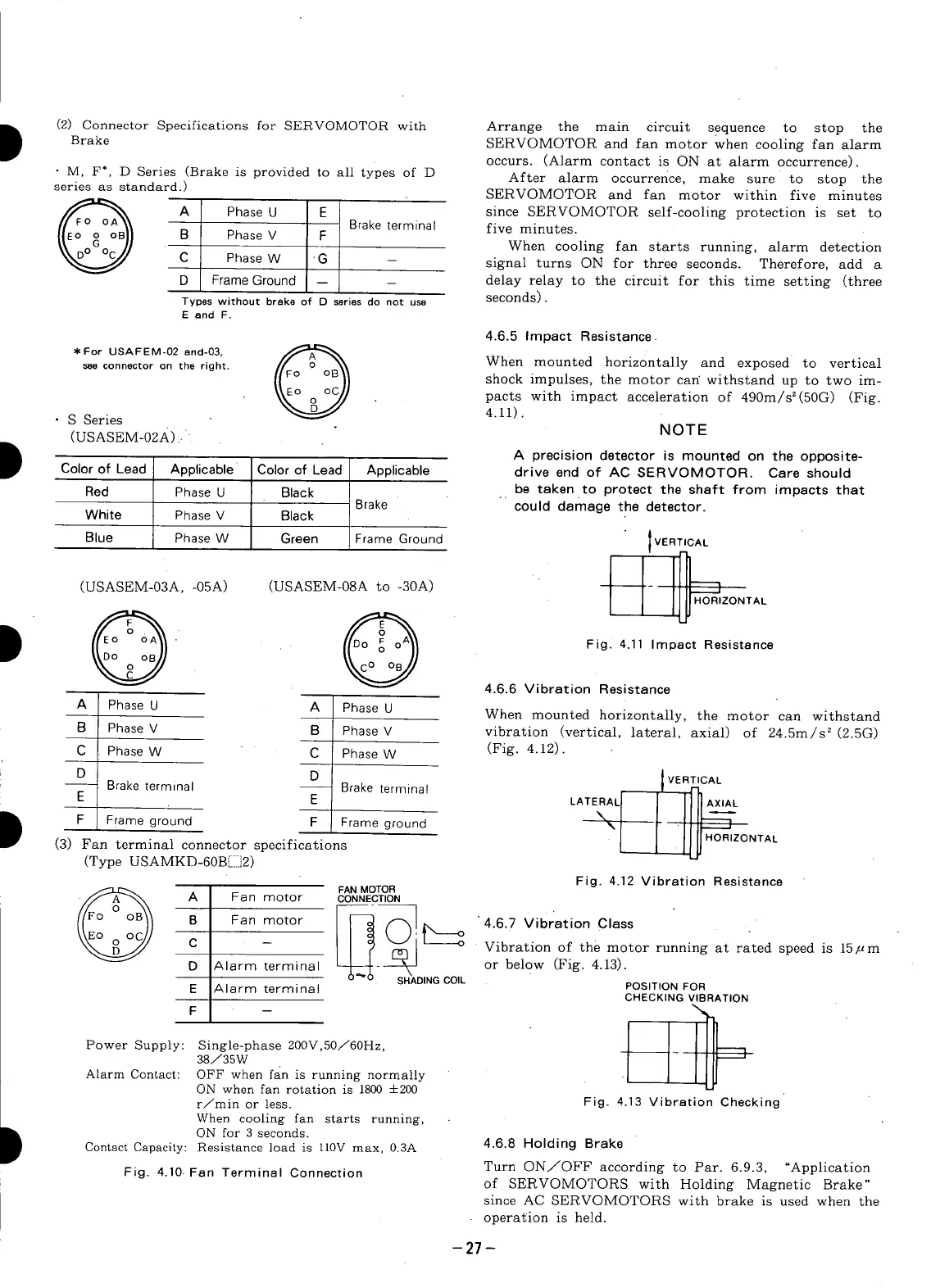
(3) Fan terminal connector specifications [L_ HORIZONTAL
(Type USAMKD-60BEI]2)
Fig. 4.12 Vibration Resistance
A Fan motor CONNECTION
B Fan motor 4.6.7 Vibration Class
C - Vibration of the motor running at rated speed is 15/_m
D Alarm terminal - or below (Fig. 4.13).
SHADING COIL
E Alarm terrain,31 POSITION FOR
CHECKING VIBRATION
F -- I IPower Supply: Single-phase 200V,50/60Hz, __
Alarm Contact: OFF when fan is running normally
ON when fan rotation is 1800 +200
r/min or less. Fig. 4.13 Vibration Checking
When cooling fan starts running,
I ONfor 3 seconds.
Contact Capacity: Resistance load is ll0V max, 0.3A 4.6.8 Holding Brake
Fig. 4.10. Fan Terminal Connection Turn ON/OFF according to Par. 6.9.3, "Application
of SERVOMOTORS with Holding Magnetic Brake"
since AC SERVOMOTORS with brake is used when the
operation is held.
-27-