D 6.6 LED INDICATION 6.7.2 Load Inertia (JL)
The allowable load moment of inertia JL converted to
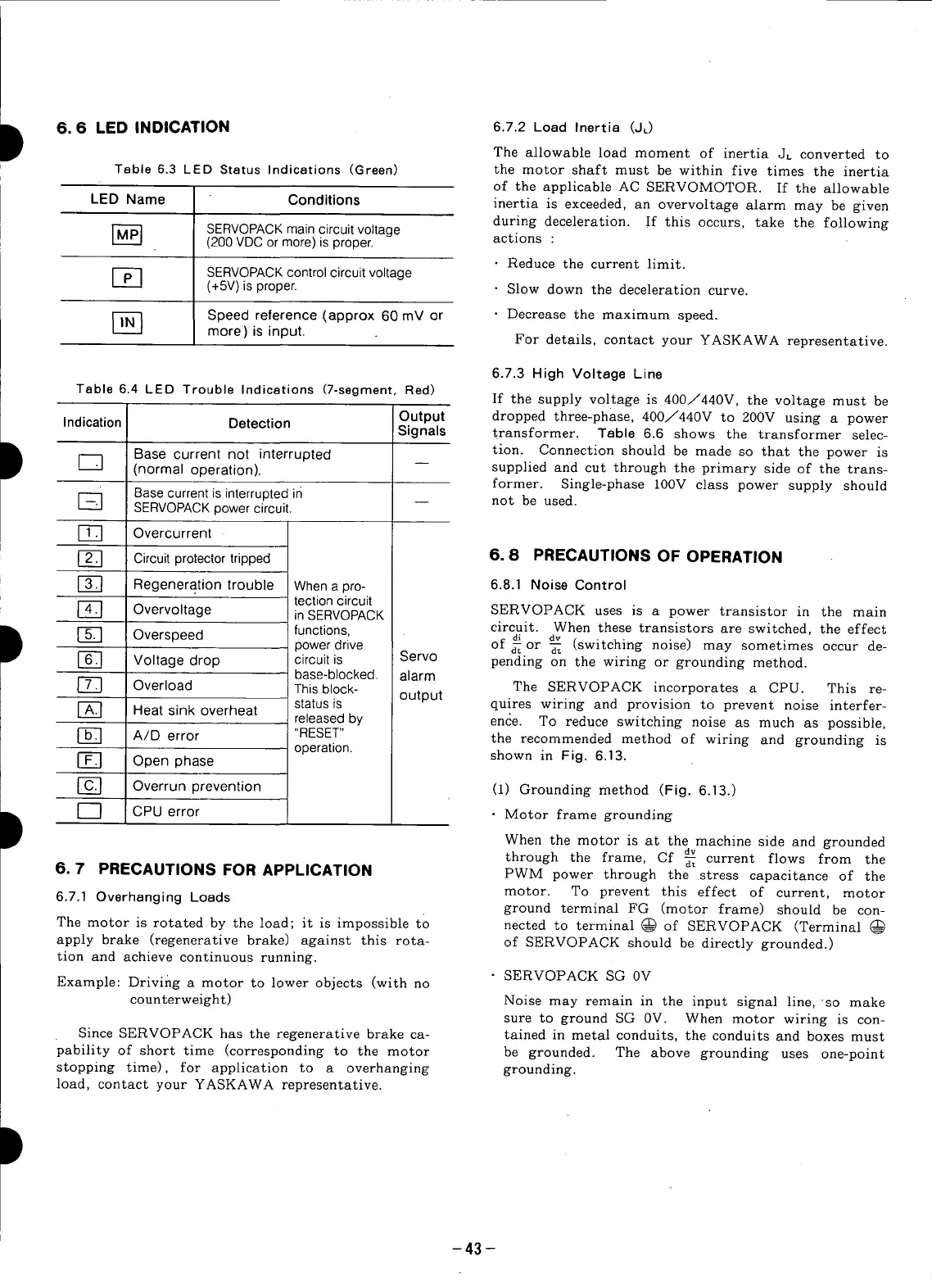
Table 6.3 LED Status Indications (Green) the motor shaft must be within five times the inertia
of the applicable AC SERVOMOTOR. If the allowable
LED Name Conditions inertia is exceeded, an overvoltage alarm may be given
during deceleration. If this occurs, take the following
r_ SERVOPACK main circuit voltage
(200 VDC or more) is proper, actions :
• Reduce the current limit.
_-_ SERVOPACK control circuit voltage
(+5V)is proper. • Slow down the deceleration curve.
Speed reference (approx 60 mV or • Decrease the maximum speed.
more) is input. For details, contact your YASKAWA representative.
6.7.3 High Voltage Line
Table 6.4 LED Trouble Indications (7-segment, Red)
If the supply voltage is 400/440V, the voltage must be
Indication Detection Output dropped three-phase, 400/440V to 200V using a power
Signals transformer. Table 6.6 shows the transformer selec-
D r-_ Base current not interrupted tion. Connection should be made so that the power is
_-_ (normal operation), supplied and cut through the primary side of the trans-
former. Single-phase 100V class power supply should
Base current is interrupted in not be used.
SERVOPACK power circuit.
[-_ Overcurrent
_] Circuit protector tripped 6. 8 PRECAUTIONS OF OPERATION
[-_ Regeneration trouble When a pro- 6.8.1 Noise Control
tection circuit
Overvoltage inSERVOPACK SERVOPACK uses is a power transistor in the main
D r_ Overspeed functions, circuit. When these transistors are switched, the effect
di dv
power drive of _ or _ (switching noise) may sometimes occur de-
r-_ Voltage drop circuit is Servo pending on the wiring or grounding method.
base-blocked, alarm
[-_ Overload This block- The SERVOPACK incorporates a CPU. This re-
r-_ Heat sink overheat status is output quires wiring and provision to prevent noise interfer-
released by ence. To reduce switching noise as much as possible,
A/D error "RESET" the recommended method of wiring and grounding is
operation, shown in Fig. 6.13.
[-_ Open phase
[_] Overrun prevention (1) Grounding method (Fig. 6.13.)
D I ] CPUerror • Motor frame grounding
When the motor is at the machine side and grounded
dv
through the frame, Cf _ current flows from the
6, 7 PRECAUTIONS FOR APPLICATION PWM power through the stress capacitance of the
6.7.1 Overhanging Loads motor. To prevent this effect of current, motor
ground terminal FG (motor frame) should be con-
The motor is rotated by the load; it is impossible to nected to terminal @ of SERVOPACK (Terminal
apply brake (regenerative brake) against this rota- of SERVOPACK should be directly grounded.)
tion and achieve continuous running.
Example: Driving a motor to lower objects (with no SERVOPACK SG 0V
counterweight) Noise may remain in the input signal line, so make
sure to ground SG 0V. When motor wiring is con-
Since SERVOPACK has the regenerative brake ca- tained in metal conduits, the conduits and boxes must
pability of short time (corresponding to the motor be grounded. The above grounding uses one-point
stopping time), for application to a overhanging grounding.
load, contact your YASKAWA representative.
-43 -