dl
6.OPERATION NOTE 11
When the power is turned ON, a servo alarm signal
6.1 POWER ON AND OFF continues for approximately 1 second (normally 200 to
300 ms) to initialize the SERVOPACK.
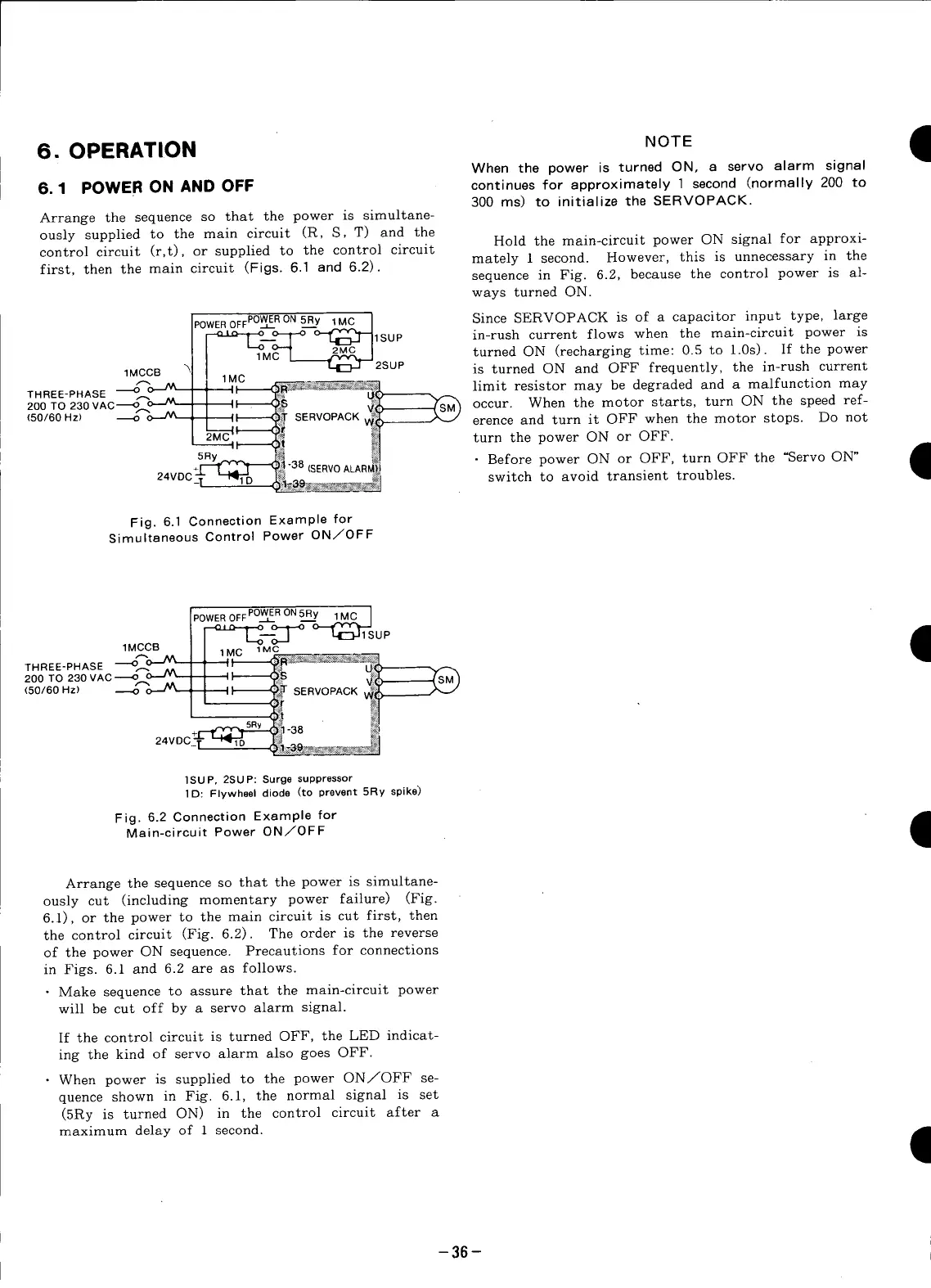
Arrange the sequence so that the power is simultane-
ously supplied to the main circuit (R, S, T) and the
Hold the main-circuit power ON signal for approxi-
control circuit (r,t), or supplied to the control circuit
first, then the main circuit (Figs. 6.1 and 6.2) mutely 1 second. However, this is unnecessary in the
• sequence in Fig. 6.2, because the control power is al-
ways turned ON.
POWEROFFPOW__ERON5Ry 1MC I Since SERVOPACK is of a capacitor input type, large
__.o-_ _lSUP in-rush current flows when the main-circuit power is
I[ 1Mc_'MC'-'-- T _21_MC ]2SUP turned ON (recharging time: 0.5 to 1.0s). If the power
1MCCB is turned ON and OFF frequently, the in-rush current
! ,, _, limit resistor may be degraded and a malfunction may
THREE-PHASE _ 1 " _' U_
200 TO 230 VAC_r__ I II (_ __SM_ Occur. When the motor starts, turn ON the speed ref-
(50/60 Hz) _ ;-_ , I _ 6_ SERVOPACK ,,_
I I _ ,_ - - erence and turn it OFF when the motor stops. Do not
2MC' "f_ _:_ turn the power ON or OFF.
------_, q_! #] ,_m
5RY_v_____.38 _1 " Before power ON or OFF, turn OFF the "Servo ON"
q
+I'_[ :_: ]'_Y_t -o,-, (SERVO ALARM}j
24VDC_. _ I_.___ _, switch to avoid transient troubles•
Fig. 6.1 Connection Example for
Simultaneous Control Power ON/OFF
POWER OFF POWER ON 5Ry 1 MC
---_D.____O O--_1 Up t
1MCCB 1MC 1MC
200TO230VAC----_o--'L'- ,I _S _----_JSM)
( o.6oH , ,, S .OPA¢
+_ !_1-38 _
24voc_i-"-_% .Ji! _
]SUP, 2SUP: Surge suppressor
1 D: Flywheel diode (to prevent 5Ry spike)
Fig. 6.2ConnectionExamplefor
Main-circuit Power ON/OFF
I
Arrange the sequence so that the power is simultane-
ously cut (including momentary power faiture) (Fig.
6.1), or the power to the main circuit is cut first, then
the control circuit (Fig. 6.2). The order is the reverse
of the power ON sequence. Precautions for connections
in Figs. 6.1 and 6.2 are as follows.
• Make sequence to assure that the main-circuit power
will be cut off by a servo alarm signal.
If the control circuit is turned OFF, the LED indicat-
ing the kind of servo alarm also goes OFF.
• When power is supplied to the power ON/OFF se-
quence shown in Fig. 6.1, the normal signal is set
(5Ry is turned ON) in the control circuit after a
maximumdelay of 1 second•
-36-