6.5 PROTECTIVE CIRCUIT (3) Servo alarm output [ALM+, ALM-] I
If any trouble detection circuits in Table 6.2 functions,
SERVOPACK provides functions to protect the body the power drive circuit in the SERVOPACK goes OFF,
and motor from malfunctions. 7-segments LED indicate the operation condition and a
(1) Dynamic brake function servo alarm signal is output.
SERVOPACK incorporates a dynamic brake for emer- (4) Protective circuit operation
gency stop. This brake operates when:
An alarm signal indicates some trouble. Check the
Alarm (fault detection) occurs, cause and correct the trouble, and restart the operation.
• Servo ON command is opened. Before checking the cause, turn OFF the power to the
main circuit to avoid danger. Apply the sequence so
• Main power supply is tuned OFF. that the alarm signal turns OFF only the main circuit
Normally, this dynamic brake is not applied while the (@, @, (2)), as shown in Figs. 6.1 and 6.2. This allows
motor stops, but can operate by switching built-in rapid reaction in the event of a malfunction.
switch (SW 4-5) from OFF to ON. Use this function If the power to the control circuit (@, @) is simul-
only in emergency. Don't use the dynamic brake to taneously turned OFF, this also turns OFF the LED in
stop the motor normally, the SERVOPACK indicating the cause of the alarm sig-
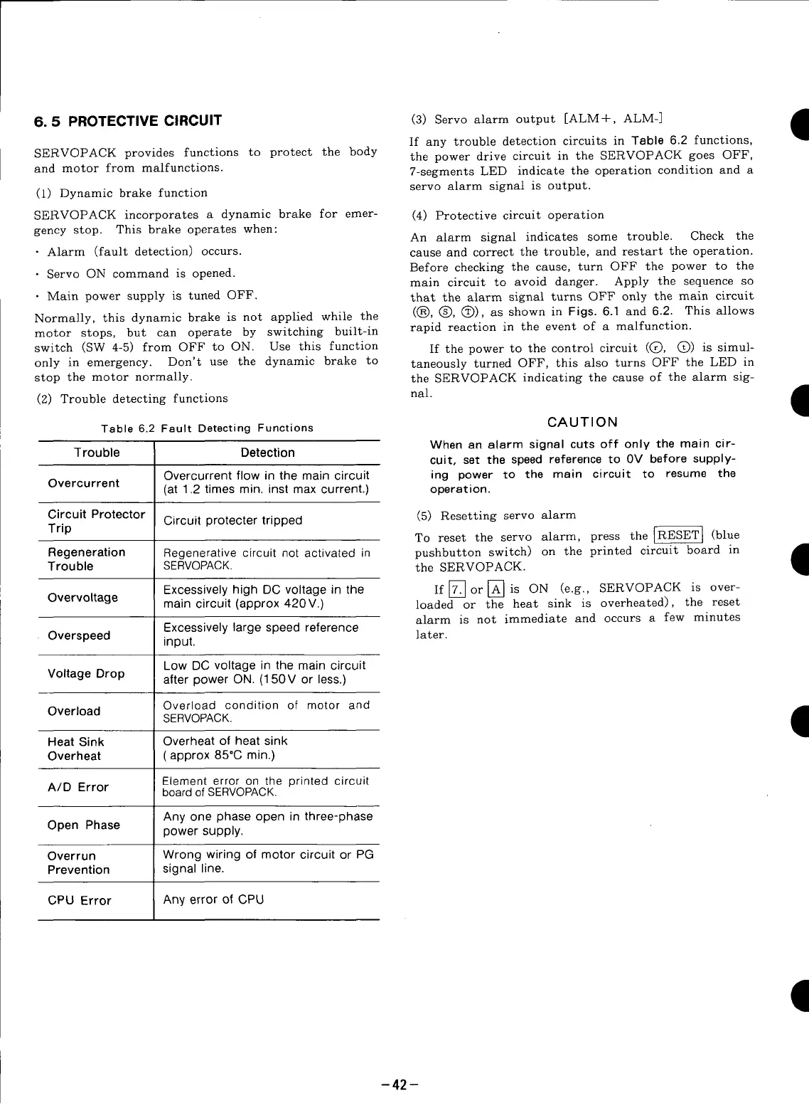
(2)Troubledetectingfunctions nal. I
Table 6.2 Fault Detecting Functions CAUTION
When an alarm signal cuts off only the main cir-
Trouble Detection
cuit, set the speed reference to 0V before supply-
Overcurrent flow in the main circuit ing power to the main circuit to resume the
Overcurrent (at 1.2 times min. inst max current.) operation.
Circuit Protector Circuit protecter tripped (5) Resetting servo alarm
Trip
To reset the servo alarm, press the _ (blue
Regeneration Regenerative circuit not activated in pushbutton switch) on the printed circuit board in •
Trouble SERVOPACK. the SERVOPACK.
I
Excessively high DC voltage in the If [_] or [_] is ON (e.g., SERVOPACK is over-
Overvoltage main circuit (approx 420V.) loaded or the heat sink is overheated), the reset
alarm is not immediate and occurs a few minutes
Excessively large speed reference
• Overspeed input, later.
Low DC voltage in the main circuit
Voltage Drop after power ON. (150V or less.)
Overload Overload condition of motor and
SERVOPACK.
Heat Sink Overheat of heat sink
Overheat (approx 85°C min.)
Element error on the printed circuit
A/D Error board of SERVOPACK.
Any one phase open in three-phase
Open Phase
power supply.
Overrun Wrong wiring of motor circuit or PG
Prevention signal line.
CPU Error Any error of CPU
-42 -