YASKAWA TOEP YAIQPM 01A iQpump Micro Quick Start Procedure
iQpump Micro
Quick Start Procedure
Page 10
of 31
Install the 24 V Transducer Power Supply (continued)
5
STEP
Note: The lower terminal cover is required for secure mounting of the 24V Power Supply on the models shown in Table 1.4. Contact
your Yaskawa representative for ordering if you have a model listed in Table 1.4 and the lower terminal cover is not present
on your drive.
Table 1.4 Lower Terminal Cover Part Number by Model
Drive Model Terminal Cover Part Number
BV0006 and BV0010
2V0010 and 2V0012
4V0002 to 4V0009
CVST31300
BV0012
2V0020
4V0011
CVST31301
Other models Not required
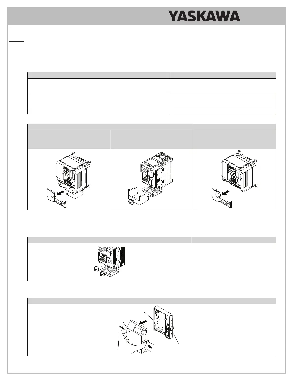
Table 1.5 Remove the Bottom Cover and Lower Terminal Cover
IP20/NEMA 1, UL Type 1 IP66/NEMA 4X, UL Type 4X
Lower Terminal Cover on All Models
Except Models:
BV0001 to BV0003
2V0001 to 2V0006
Bottom Cover on All Models Terminal Cover on Models
BV0006G to BV0010G
2V0010G to 2V0020G
4V0002G to 4V0011G
5.9
On IP20/NEMA 1, UL Type 1 enclosure models, loosen the screws attaching the NEMA 1, UL Type 1 conduit bracket
to the drive to allow the bracket to swing out to provide easier access to the ground screw. Do not remove the
screws.
Table 1.6 Loosen Conduit Bracket Screws
IP20/NEMA 1, UL Type 1 IP66/NEMA 4X, UL Type 4X
Not applicable.
5.10
Remove the 24V Power Supply cover.
Table 1.7 Remove 24V Power Supply Cover
IP20/NEMA 1, UL Type 1 and IP66/NEMA 4X, UL Type 4X
24V Power Supply Cover
Mounting Tab
Mounting Slot
Mounting Slot
Mounting Tab