YASKAWA TOEP YAIQPM 01A iQpump Micro Quick Start Procedure
iQpump Micro
Quick Start Procedure
Page 9
of 31
Install the 24 V Transducer Power Supply (continued)
5
STEP
5.6 Installation Procedure
5.7
Shut off power to the drive. Wait at least five minutes after confirming the DC bus voltage is safe.
On IP20/NEMA 1, UL Type 1 models, loosen the screw that fastens the front cover in place and remove the front
cover. This drive front cover will be replaced by the 24V Power Supply cover. Cover removal varies depending on
drive size.
On IP66/NEMA 4X, UL Type 4X models, loosen the 4 bolts that attach the enclosure front cover in place, gently
move the front cover away from the enclosure, press firmly on the digital operator cable connector release tab to
disconnect the cable from port CN1 on the drive, then remove the front cover. Refer to Table 1.3 for installation bolt
size.
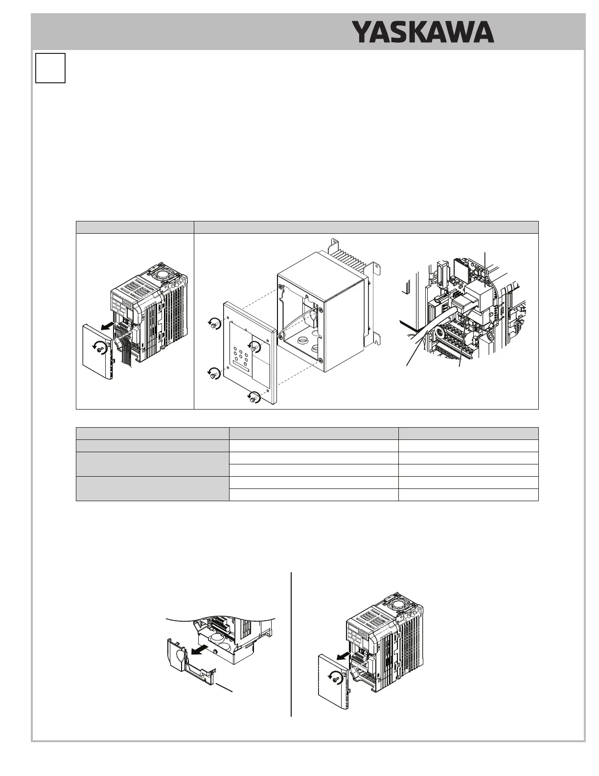
Table 1.2 Remove the Drive or Enclosure Front Cover
IP20/NEMA 1, UL Type 1 IP66/NEMA 4X, UL Type 4X
Digital
Operator
Cable
Port
CN1
Connector
Release Tab
Table 1.3 IP66/NEMA 4X, UL Type 4X Enclosure Front Cover Installation Bolt Size
Voltage Class Drive Model Installation Bolt Size
Single-Phase 200 V Class BV0001G to BV0012G M5
Three-Phase 200 V Class
2V0001G to 2V0020G M5
2V0030G to 2V0069G M6
Three-Phase 400 V Class
4V0001G to 4V0011G M5
4V0018G to 4V0038G M6
5.8
On IP20/NEMA 1, UL Type 1 enclosure models, loosen the screw on the front of the bottom cover and remove it from
the drive. All models except 2V0006F require removing a plastic lower terminal cover prior to removing the bottom
cover.
On IP66/NEMA 4X, UL Type 4Xenclosure models, remove the lower terminal cover (if provided) from the drive.
The lower terminal cover is not present on certain models.
Models Without
Lower Terminal Cover:
BV0001 to BV0003 and
2V0001 to 2V0006
Models With
Lower Terminal Cover
Lower
Terminal Cover