4 Start-Up Programming & Operation
YASKAWA ELECTRIC TOEP C710616 38H YASKAWA AC Drive-L1000A Quick Start Guide 91
Start-Up Programming
& Operation
4
Set an analog input terminal for torque compensation (H3- = 14) and proceed with the steps below.
Procedure for Load Condition 1 (S3-27, S3-29)
1.
Make sure the drive is wired properly. For instructions, refer to Standard Connection Diagram on page 25.
2. Set the speed reference to 0%.
3. Apply no weight to the elevator car.
4. Note the value of the analog input monitor for the load signal input is connected to (U1-13 for terminal A1, U1-14
for terminal A2).
5. Provide an elevator Up or Down command, using Inspection Operation or normal operation mode. The car
should be held in place when the brake releases.
6. Note the drives internal torque reference monitor U1-09.
7. Stop the drive.
8. Set the value noted in step 4 to parameter S3-29. Set the value noted in step 6 to parameter S3-27.
Procedure for Load Condition 2 (S3-28, S3-30)
1.
Set the speed reference to 0%.
2. Apply load to the car has much as possible (at least 50% of the maximum weight).
3. Note the value of the analog input monitor for the load signal input connected to (U1-13 for terminal A1, U1-14 for
terminal A2).
4. Provide an elevator Up or Down command, using Inspection Operation or normal operation mode. The car
should be held in place when the brake releases.
5. Note the drives internal torque reference monitor U1-09.
6. Stop the drive.
7. Set the value noted in step 3 to parameter S3-30. Set the value noted in step 5 to parameter S3-28.
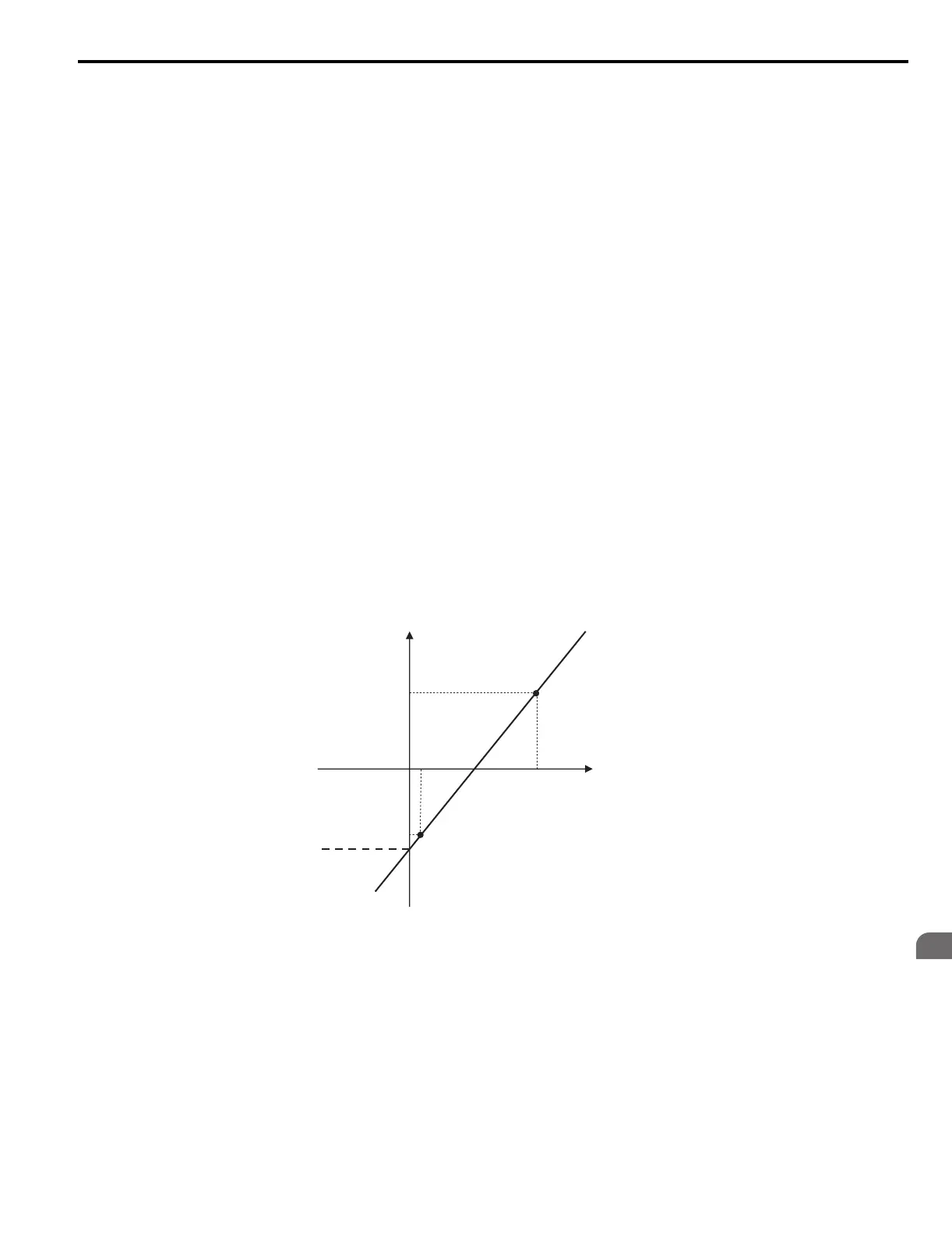
Figure 45 shows the Torque Compensation at Start settings with parameters S3-27 to S3-30.
The solid line in Figure 45 indicates the torque compensation at start when the elevator moves up or down.
Figure 40
Figure 45 Torque Compensation at start for the Elevator in Up and Down Direction
Note: PRG: 7015 or earlier will apply a limit at 0 V torque compensation input value.
PRG: 7016 or later have no torque compensation limit when adding negative voltage to analog input voltage (see Figure 45).
Analog Input Voltage (V)
S3-30
(Analog input
from Load Sensor
with Load Condition 2)
S3-29
(Analog Input from
Load Sensor
with Load
Condition 1)
S3-27
(Torque Compensation Value
with Load Condition 1)
S3-28
(Torque Compensation
Value with Load Condition 2)
0
During Load Condition 2
During Load Condition 1
Torque Compensation Value
TOEP_C710616_38H_7_0.book 91 ページ 2015年11月11日 水曜日 午後7時40分