4 I/O Signal Allocation
4.1 Setting of Optional Board and I/O Module
4-3
HW1483854
HW1483854
6. Select "J71GF11-T2 ".
– The J71GF11-T2 setup display appears.
– Set the items on the display.
Explanation of Setup Items
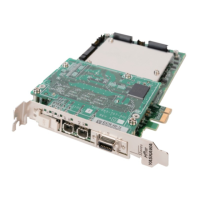
Q81BDJ71GF11-T2
Sets whether to use the J71GF11-T2 board. Set “USED”.
SLAVE OR MASTER
Displays the board operation mode. This setting can not be changed.
I/O SIZE
Sets the size of input/output (units: byte) to transmit and receive data.
Set the multiple of 2 from 2 to 256.
NETWORK NUMBER
Sets the network number of CC-Link IE Field network.
Set the number from 1 to 239.
STATION NUMBER
Sets the CC-Link IE Field network station number.
Set the number from 1 to 120.
ERROR CODE ALLOCATION
Sets the YRC1000 M-register number to be the output destination when
output the error code of CC-Link IE Field network.
Set the number from 0 to 599.
For the details of output error codes, refer to the following manual of
MITSUBISHI ELECTRIC Co., Ltd.
“CC-Link IE Field Network Interface Board User’s Manual (For
SW1DNC-CCIEF-B)”
REMOTE REGISTER
Sets whether to allocate the remote register of CC-Link IE Field network
to the YRC1000 M-register.
When allocate it, set “ENABLE”.
REMOTE REGISTER SIZE
Sets the allocation number of remote register of CC-Link IE Field net-
work to the YRC1000 M-register. The same number set here can be
allocated for both input and output.
Set the multiple of 4 from 4 to 276.

 Loading...


