4.4 MP2000 Series Machine Controller Parameter Details
4.4.2 Motion Setting Parameter Details
4-57
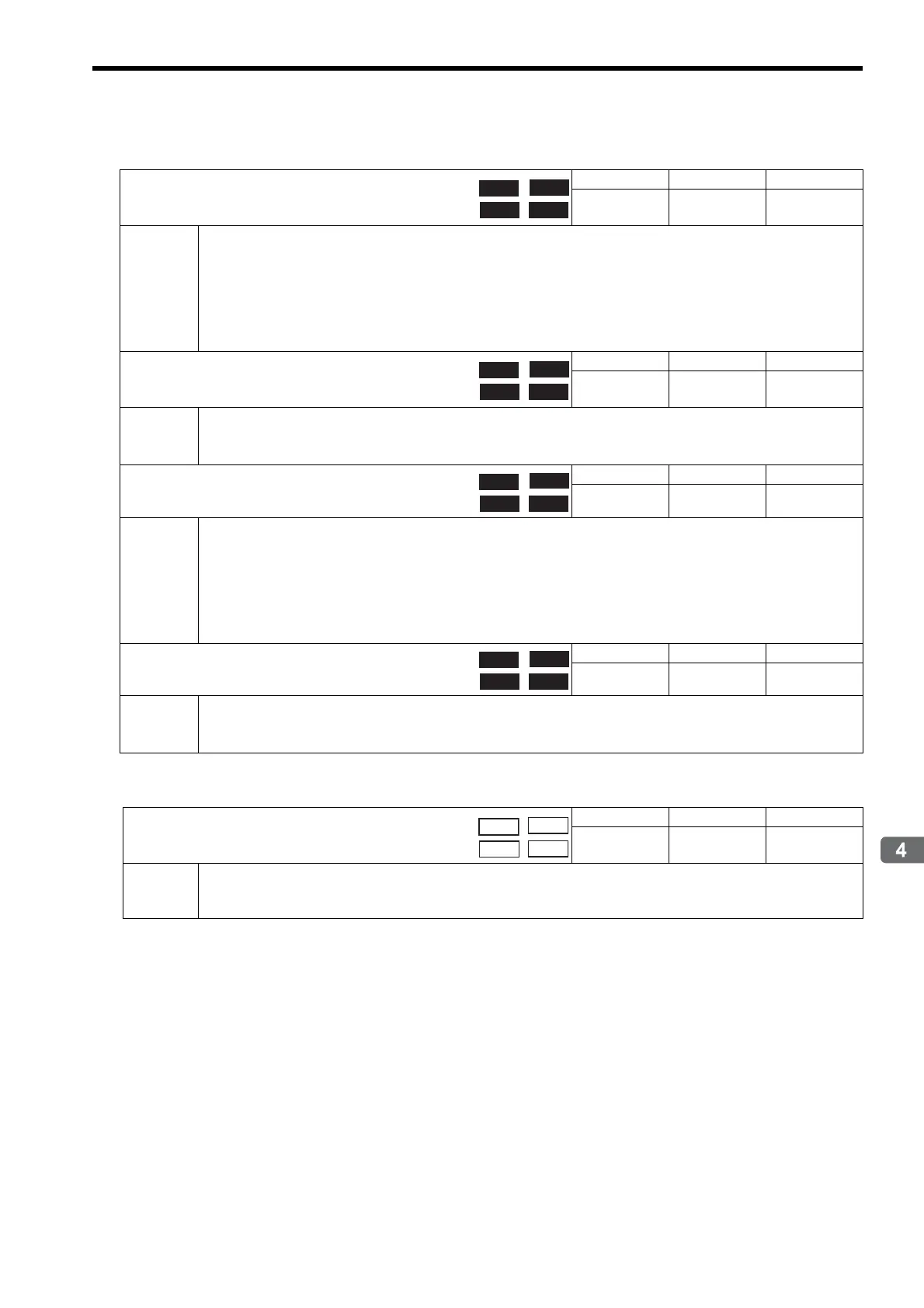
( 32 ) Absolute Infinite Length Axis Position Control Information
( 33 ) Command Buffer for Servo Driver Transmission Reference Mode
OL5E
Encoder Position when Power is OFF
(Lower 2 words)
Setting Range Setting Unit Default Value
-2
31
to 2
31
−1
pulse 0
Description
This is the information for infinite length axis position control when an absolute encoder is used.
The encoder position is stored in 4 words.
If the Request ABS Rotary Pos LOAD bit is set to 1 in the RUN Command Setting (setting parameter OW00, bit 7),
the position information will be recalculated with the values set here and the Pulse Position when Power is OFF
(OL62 and OL64).
Refer to 9.4 Absolute Position Detection for Infinite Length Axes for details.
Set to 0 for linear type.
OL60
Encoder Position when Power is OFF
(Upper 2 words)
Setting Range Setting Unit Default Value
-2
31
to 2
31
−1
pulse 0
Description
Same as for OL5E.
Refer to 9.4 Absolute Position Detection for Infinite Length Axes for details.
Set to 0 for linear type.
OL62
Pulse Position When Power is OFF (Lower 2 words)
Setting Range Setting Unit Default Value
-2
31
to 2
31
−1
pulse 0
Description
This is the information for infinite length axis position control when an absolute encoder is used.
The axis position in pulses managed internally by the controller is stored in 4 words.
If the Request ABS Rotary Pos. LOAD bit is set to 1 in the Run Command Setting (setting parameter OW00, bit 7),
the position information will be recalculated with the values set here and the Encoder Position when Power is OFF
(OL5E and OL60).
Refer to 9.4 Absolute Position Detection for Infinite Length Axes for details.
Set to 0 for linear type.
OL64
Pulse Position When Power is OFF (Upper 2 words)
Setting Range Setting Unit Default Value
-2
31
to 2
31
−1
pulse 0
Description
Same as for OL62.
Refer to 9.4 Absolute Position Detection for Infinite Length Axes for details.
Set to 0 for linear type.
OW70 to OW7E
Command Buffer for Servo Driver Transmission
Reference Mode
Setting Range Setting Unit Default Value
−−0
Description
This area is used for response data when MECHATROLINK Servo commands are specified directly.
• MECHATROLINK-I and MECHATROLINK-II, 17-byte Mode: Data area = OW70 to OW77
• MECHATROLINK- II, 32-byte Mode: Data area = OW70 to OW7E
Position