5 Installation Procedure
20 YASKAWA ELECTRIC SIEP C730600 70B V1000 Option SI-EP3/V Technical Manual
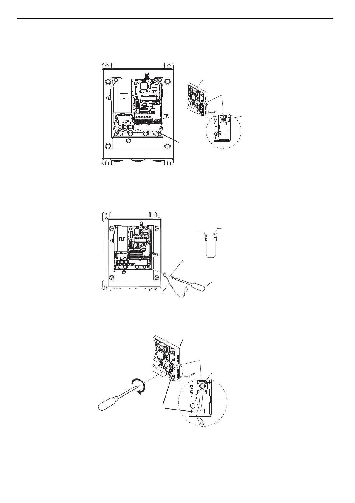
13. For IP66/UL Type 4X enclosure models, remove the drive ground terminal screw and option ground terminal
screw (see Figure 16.)
Note: The screw for the drive ground terminal also acts as one of the screws that attaches the waterproof/dust-proof enclosure to the
drive.
Figure 16
Figure 16 Remove IP66/UL Type 4X Ground Terminal Screw
14. For IP66/UL Type 4X enclosure models, reattach the drive ground terminal screw according to Figure 17.
Note: 1. The screw for the drive ground terminal also acts as one of the screws that attaches the waterproof/dust-proof enclosure to the drive.
2. The four different ground wires packaged with the option connect the option to different drive models. Select the proper ground wire
depending on drive size. Refer to Table 7 on page 16 for ground wire selection by drive model.
Figure 17
Figure 17 IP66/UL Type 4X Ground Wire Connection
15. For IP66/UL Type 4X enclosure models, pass the ground wire into the through-hole for the ground wire, in the
back of the option, and connect the ground wire at the option ground terminal (FE). Tighten the screw to 0.5 to
0.6 Nm or (4.4 to 5.3 in lbs) using an M3 Phillips screwdriver.
Figure 18
Figure 18 Ground Wire Connection Option Side
16. For IP66/UL Type 4X enclosure models, go to Step 22.on page 23.
Drive
Ground terminal
screw
Option
Drive ground
terminal screw
FE
Ground Wire
Lower-right screw
Ground wire
Drive-side
ground terminal
Screw size:
M3.5 to M6
Option ground
screw FE
Screw size: M3
Screwdriver
Option ground
terminal (FE)
Ground terminal
screw
Ground wire
Option through-hole
for ground wire
Option back side
PROFINET_E_conditional.fm 20 ページ 2016年6月20日 月曜日 午後8時2分