3.2 Specifications and Ratings
3.2.1 Specifications
3-4
SGM7D-
I and -
J
*1. Protective structure specifications apply only when the special cable is used.
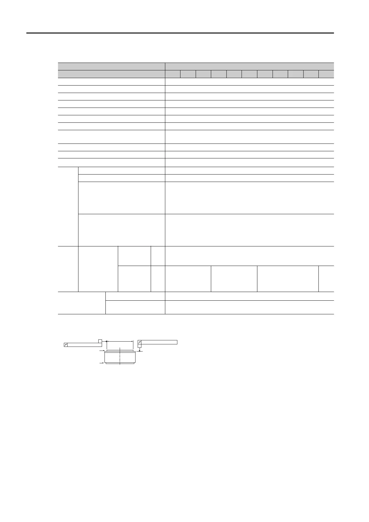
*2. Refer to the following figure for the relevant locations on the Servomotor. Refer to the dimensional drawings of
the individual Servomotors for more information on tolerances.
*3. An SGM7D Servomotor is used together with an FT-specification SERVOPACK. The following SERVOPACK
models can be used.
•
SGD7S-
A
F82
•
SGD7S-
00A
F83
Voltage 200 V
SGM7D- 28I 70I 1ZI 1CI 2BI 2DI
06J 09J 18J 20J 38J
Time Rating Continuous
Thermal Class F
Insulation Resistance 500 VDC, 10 MΩ min.
Withstand Voltage 1,500 VAC for 1 minute
Excitation Three-phase
Mounting Flange-mounted
Drive Method Direct drive
Rotation Direction
Counterclockwise (CCW) for forward reference when viewed from
the load side
Absolute Accuracy ±15 s
Repeatability ±1.3 s
Protective Structure
*1
Totally enclosed, self-cooled, IP30
Environmental Conditions
Surrounding Air Temperature 0°C to 40°C (with no freezing)
Surrounding Air Humidity 20% to 80% relative humidity (with no condensation)
Installation Site
• Must be indoors and free of corrosive and explosive gases.
• Must be well-ventilated and free of dust and moisture.
• Must facilitate inspection and cleaning.
• Must have an altitude of 1,000 m or less.
• Must be free of strong magnetic fields.
Storage Environment
Store the Servomotor in the following environment if you store it
with the power cable disconnected.
Storage Temperature: -20°C to 60°C (with no freezing)
Storage Humidity: 20% to 80% relative humidity (with no conden-
sation)
Mech-
anical
Tol e r-
ances
*2
Runout of
Output Shaft
Surface/
Runout at
End of Output
Shaft
Standard
Mechanical
Precision
mm 0.1
High
Mechani-
cal Preci-
sion
mm 0.005 0.02 0.005 0.01
Applicable
SERVOPACKs
SGD7S-
120A
*3
SGD7W-
SGD7C-
–
A
B
Load side
Non-load side
Runout of output shaft surface
Runout at end of output shaft
dia.
: Diameter determined by motor model.