9 Adjustments
9.1.3 Monitoring Analog Signals
9-6
(3) Setting Monitor Factor
The output voltages on analog monitors 1 and 2 are calculated by the following equations.
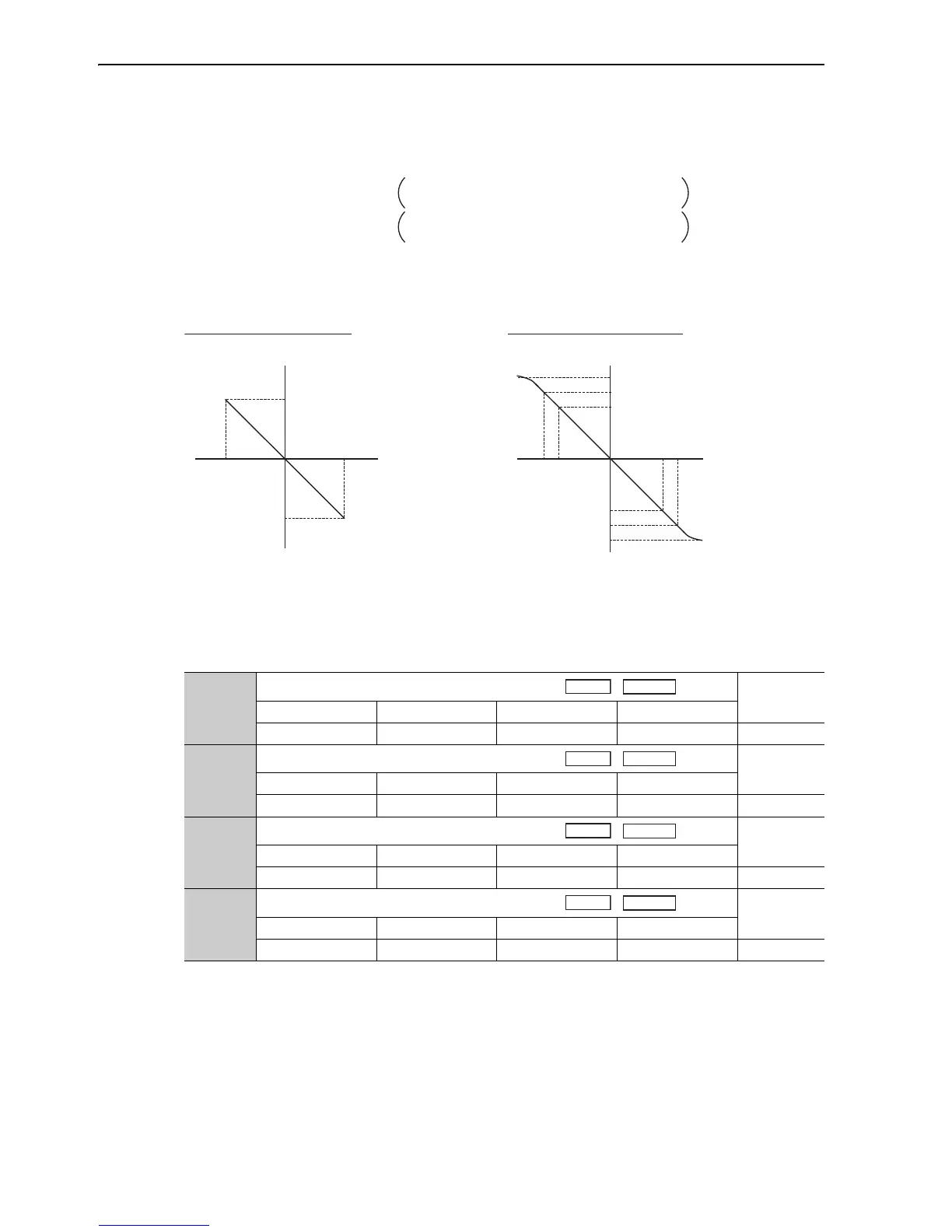
<Example>
Analog monitor output at n.00 (motor speed setting)
(4) Related Parameters
Use the following parameters to change the monitor factor and the offset.
Analog monitor 1 output voltage = (-1) × Signal selection
(Pn006=n.00!!)
(Pn552)
Analog monitor 2 output voltage = (-1)
× Signal selection
(Pn007=n.00!!)
× Multiplier + Offset voltage [V]
× Multiplier + Offset voltage [V]
(Pn550)
(Pn551)
(Pn553)
+6 V
-6 V
-600
+600
+8 V
-8 V
-800
+800
+10 V (approx.)
-10 V (approx.)
+6 V
-6 V
-6000
+6000
Analog monitor
output voltage [V]
Analog monitor
output voltage[V]
When multiplier is set to × 1: When multiplier is set to × 10:
Motor speed
[min
-1
]
Motor speed
[min
-1
]
Note: Linear effective range: within ± 8 V
Output resolution: 16-bit
Pn550
(2116h:1)
Analog Monitor 1 Offset Voltage
Classification
Setting Range Setting Unit Factory Setting When Enabled
-10000 to 10000 0.1 V 0 Immediately Setup
Pn551
(2116h:2)
Analog Monitor 2 Offset Voltage
Classification
Setting Range Setting Unit Factory Setting When Enabled
-10000 to 10000 0.1 V 0 Immediately Setup
Pn552
(2116h:3)
Analog Monitor Magnification (× 1)
Classification
Setting Range Setting Unit Factory Setting When Enabled
-10000 to 10000 × 0.01 100 Immediately Setup
Pn553
(2116h:4)
Analog Monitor Magnification (× 2)
Classification
Setting Range Setting Unit Factory Setting When Enabled
-10000 to 10000 × 0.01 100 Immediately Setup
Speed
 Loading...


