6 Parameter Table
YASKAWA Europe TOEP C710606 101A - V1000 MMD IP65 Motor Mounted Drive - Quick Start Guide EN 41
ENGLISH
n8-65
<2>
Speed Feed-
back Detec-
tion Control
Gain dur-
ing ov Sup-
pression
Sets the gain used for internal
speed feedback detection during ov
Suppression
<1> Values shown here are for 200 V class drives. Double
the value when using a 400 V class drive.
<2> Available in drive software 1011 and later.
Monitor Description
U1-01 Frequency Reference (Hz)
U1-02 Output Frequency (Hz)
U1-03 Output Current (A)
U1-05 Motor Speed (Hz)
U1-06 Output Voltage Reference (Vac)
U1-07 DC Bus Voltage (Vdc)
U1-08 Output Power (kW)
U1-09 Torque Reference (% of motor rated torque)
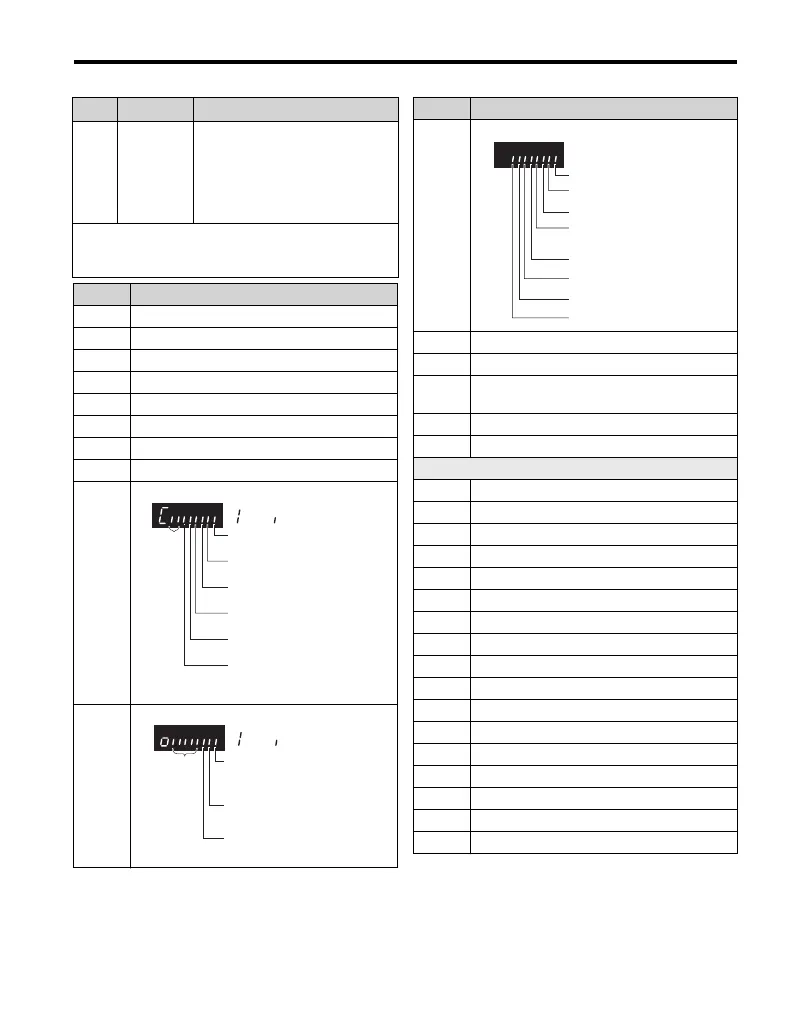
U1-10
Input Terminal Status
U1-11
Output Terminal Status
Par. Name Description
1: Digital input 1
(terminal S1 enabled)
1: Digital input 2
(terminal S2 enabled)
1: Digital input 3
(terminal S3 enabled)
1: Digital input 4
(terminal S4 enabled)
1: Digital input 5
(terminal S5 enabled)
1: Digital input6
(terminal S6 enabled)
: ON : OFF
Reserved
1: Relay Output
(terminal MA-MC closed
MB-MC open)
1: Open Collector Output 1
(terminal P1) enabled
1: Open collector Output 2
(terminal P2) enabled
: ON
Reserved
: OFF
U1-12
Drive Status
U1-13 Terminal A1 input level
U1-14 Terminal A2 input level
U1-16
Soft Starter Output (freq after accel/decel
ramps)
U1-18 OPE Fault Parameter
U1-24 Pulse Input frequency
Fault Trace
U2-01 Current Fault
U2-02 Previous Fault
U2-03 Frequency Reference at Previous Fault
U2-04 Output Frequency at Previous Fault
U2-05 Output Current at Previous Fault
U2-06 Motor Speed at Previous Fault
U2-07 Output Voltage at Previous Fault
U2-08 DC Bus Voltage at Previous Fault
U2-09 Output Power at Previous Fault
U2-10 Torque Reference at Previous Fault
U2-11 Input Terminal Status at Previous Fault
U2-12 Output Terminal Status at Previous Fault
U2-13 Drive Operation Status at Previous Fault
U2-14 Cumulative Operation Time at Previous Fault
U2-15 Soft-Starter Speed Reference at Previous Fault
U2-16 Motor q-Axis Current at Previous Fault
U2-17 Motor d-Axis Current at Previous Fault
Monitor Description
1: During run
1: During zero-speed
1: During REV
1: During fault reset
signal input
1: During speed agree
1: Drive ready
1: During alarm detection
1: During fault detection
WWW.NNC.IR

 Loading...