4 CANopen Option Components
10 YASKAWA ELECTRIC SIEP C730600 24A V1000 Option CANopen Technical Manual
◆ Communication connector
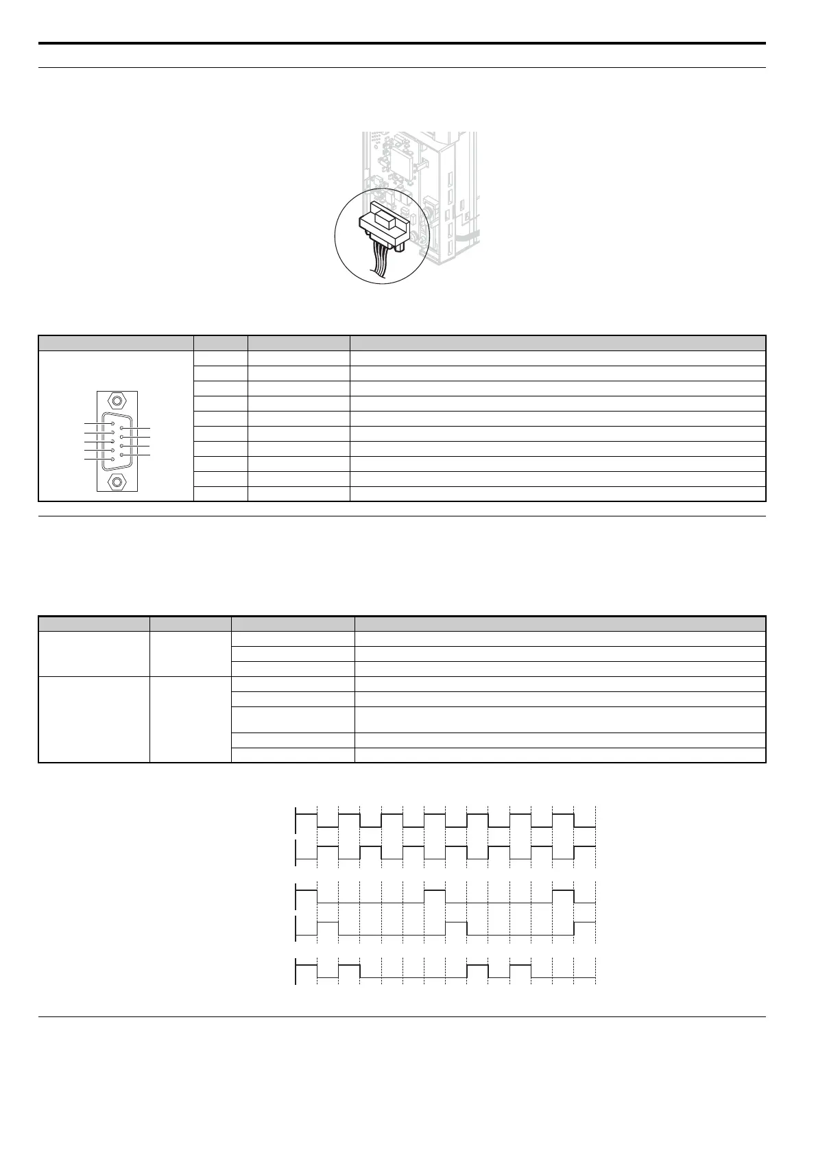
The SI-S3/V is connected to the network using a 9 pin D-SUB connector. The connector location is illustrated in Figure 3, the pin assignment is
explained in Table 3.
Figure 4
Figure 3 Communication connector location
Table 3 Communication connector (9 pin D-SUB)
◆ CANopen Option LED Display
The SI-S3/V has two LEDs that indicate the Option unit or communication status. The indications are conform with the DS303, Part 3: Indicator
Specification.
■ Checking LED Operation
Table 4 LED Display
Figure 4 explains the indicator flash rates.
Figure 4 LED Flash Rates and Meaning
◆ Setting Node Address
Set the node address in the drive parameter F6-35. The node address can be set between 1 and 127 but has to be unique in the network. If the Node
address is set to 0, communications will not be possible and the ERR LED will flash.
CANopen Connector Pin Signal Description
1––
2 CAN_L CAN_L bus line (dominant low)
3 CAN_GND CAN Ground
4––
5 CAN_SHLD CAN shield
6––
7 CAN_H CAN_H bus line (dominant high)
8––
9––
– CAN_SHLD CAN shield
LED Color Display Meaning
RUN Green
On Operational State
Blinking Pre-operational State
Single flash Stopped
ERR Red
On Bus off
Blinking Bus initialization failed (parameter setting error)
Single flash
Fault has occurred
Receiving CAN error frame (too many error frames)
Double flash Guard / Heartbeat event has occurred
Off Online
1
5
6
9
Bottom View
7
8
2
3
4
Blinking
ON
1s
2s
ON
ON
ON
ON
ERR
RUN
ERR
RUN
Single flash
ERR
Double flash

 Loading...