1-2
IM 2558A-01EN
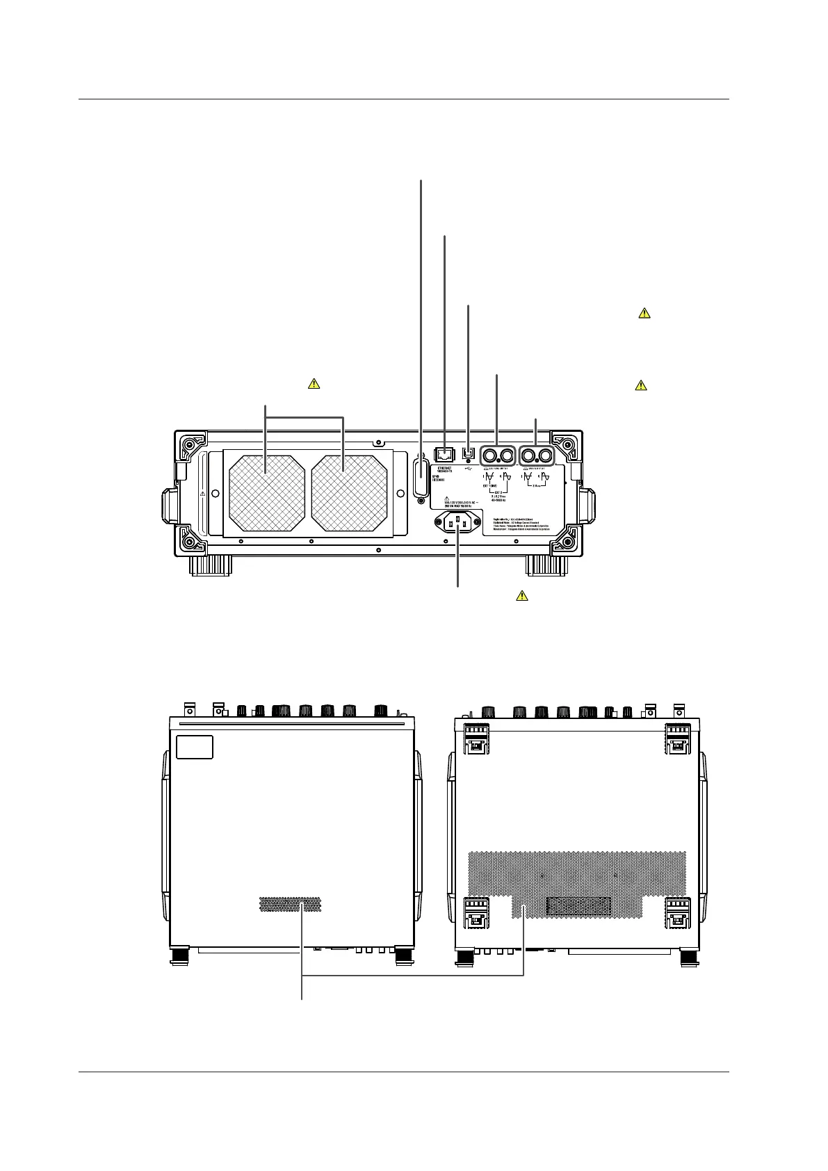
Rear Panel
Power inlet
Connect the power cord.
→ Section 3.3
Used to control the 2558A from a PC
→ Section 11.2
Ethernet port
Used to connect the 2558A to a network
(10BASE-T/100BASE-TX)
→ Section 10.2
USB port
Used to connect the 2558A to a PC that has a
USB interface and to control the 2558A with
USB-TMC commands
→ Section 9.2
External signal input terminal
Used to generate voltage or current on the
basis of an external oscillator frequency or
synchronize multiple 2558As
→ Section 7.1 and 7.2
Signal output terminals
Used to synchronize multiple 2558As
→ Sections 7.1 and 7.2
Inlet holes
→ Section 3.2
Top and Bottom Panels
Outlet holes
→ Section 3.2
1.1 Front Panel, Rear Panel, and Top Panel
 Loading...