(3) Conduit Wiring
When wiring the conduits, pass the conduit through the
wiring connection port, and utilize the waterproof gland to
preventwaterfromowingin.Placetheconduitpipeon
an angle as shown in Figure 4.4.5.
Install a drain valve at the low end of the vertical pipe, and
open the valve regularly.
Drain valve
Figure 4.4.5 Conduit Wiring
4.4.4 Wiring Connections
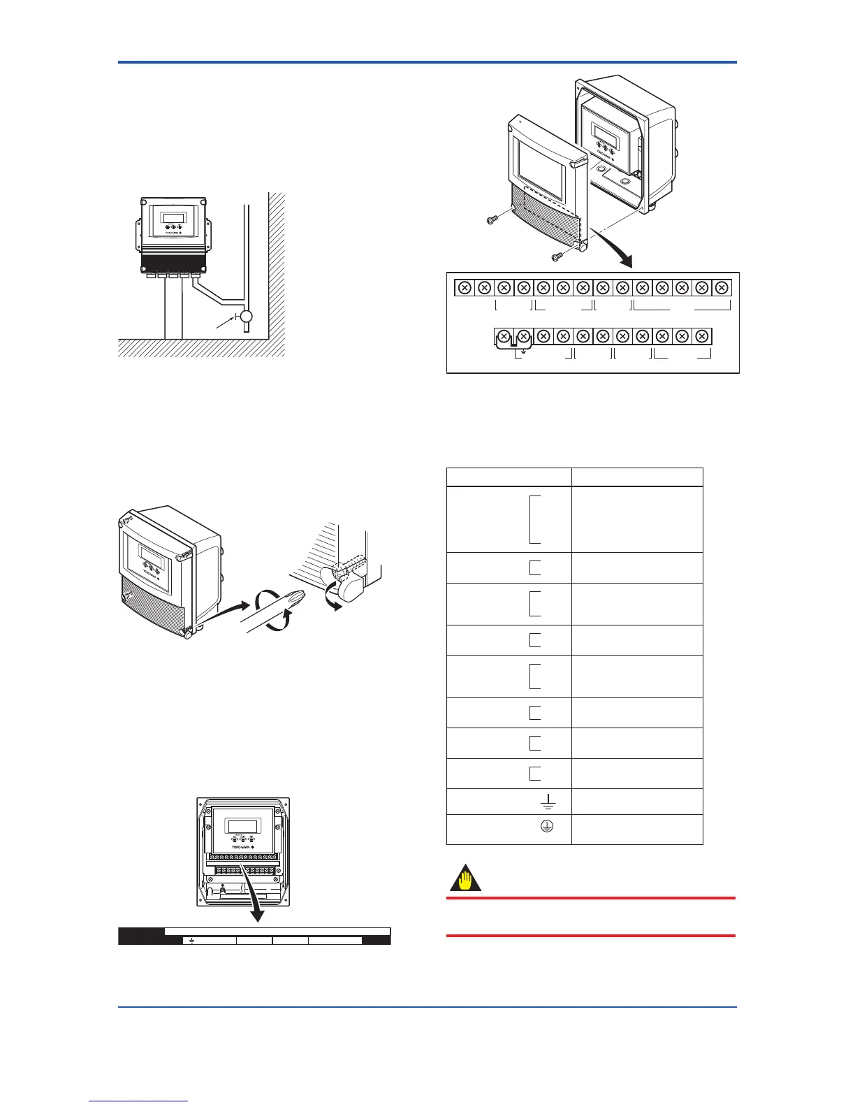
(1) Removing Cover
Whilesupportingthefrontofthecoverwithyourhand,ip
the connecting screw protective cover over, and remove
the four connecting screws.
Figure 4.4.6 Removing the Front Cover for AXFA11
Remote Converter
(2) TerminalConguration
When the cover is removed, the connection terminals
will be visible as shown in Figure 4.4.7. The terminal
congurationlabelsareattachedinthepositionshownin
Figure 4.4.8. The description of the terminal symbols is
shown in Table 4.4.1.
N/– L/+ EX2EX1 P–P+
I+ I– AL+ AL– C SA A B SB
SI1+ SI2+ COM
SO1+ COMSO2+
Figure4.4.7 TerminalCongurationforAXFA11Remote
Converter
I+ I–
CURRENT OUT
AL+ AL– C SA A B SB
ALARM OUT
N/– L/+
POWER SUPPLY
EX2EX1
EXCITATION
P–P+
PULSE OUT
SIGNAL
SI1+ SI2+ COM
STATUS IN
SO1+ COMSO2+
STATUS OUT
Figure4.4.8 TerminalCongurationLabelspositionfor
AXFA11 Remote Converter
Table 4.4.1 Terminal Symbols for AXFA11 Remote
Converter
Terminal Symbols Description
SIGNAL
C
SA
A
B
SB
Flow signal input
ALARM OUT
AL+
AL-
Alarm output
STATUS OUT
SO1+
SO2+
COM
Status output (Two output)
CURRENT OUT
I+
I-
Current output 4 to 20mA DC
STATUS IN
Sl1+
Sl2+
COM
Status input (Two input)
PULSE OUT
P+
P-
Pulse output
EXCITATION
EX1
EX2
Excitation current output
POWER SUPPLY
L /+
N/-
Power supply
Functional grounding
Protective grounding (Outside
of the terminal)
IMPORTANT
Do not wire the terminal without terminal symbols in
terminal layout labels.
 Loading...

