<2. Installation >
2-2
IM 11M10A01-01E
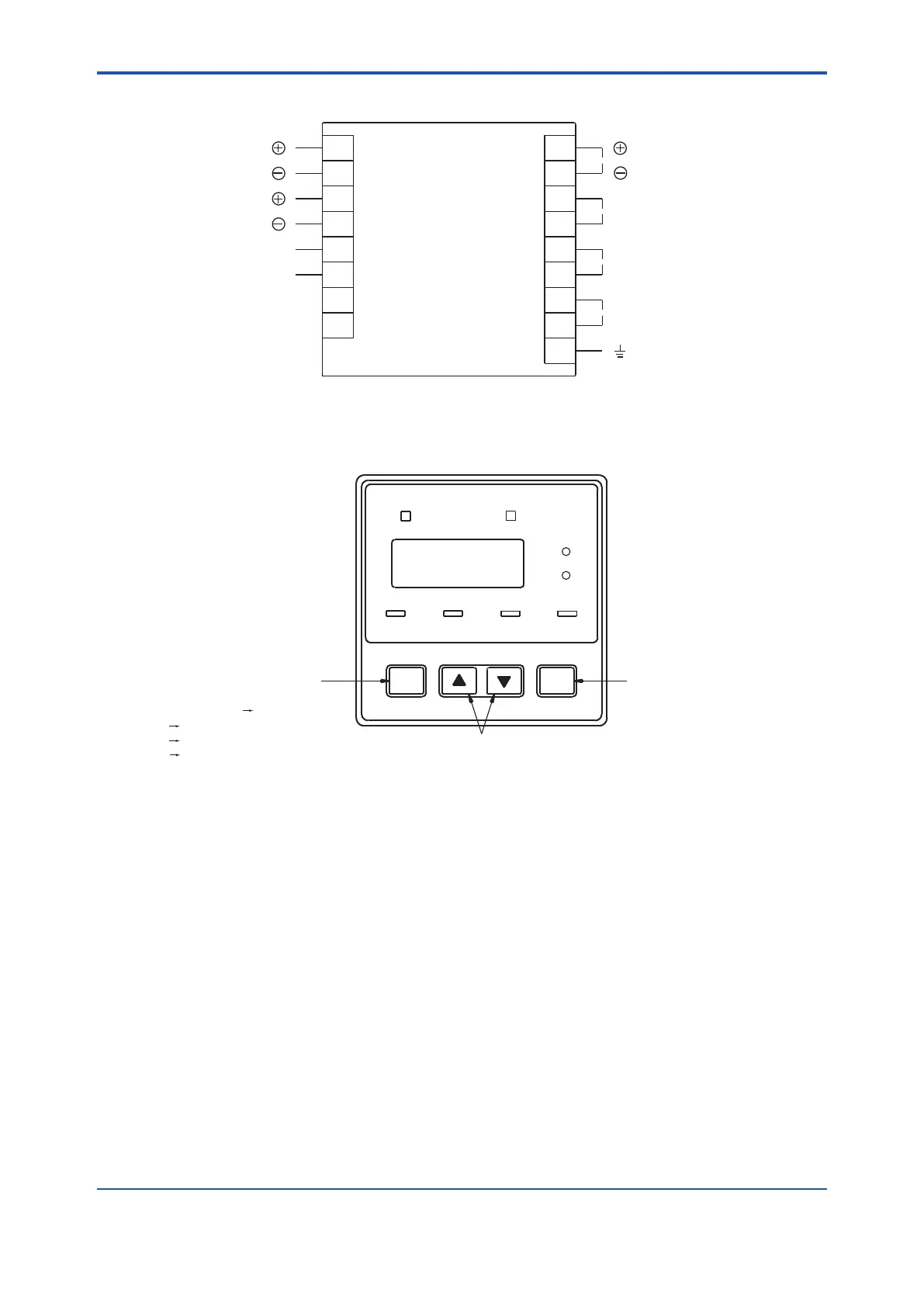
Terminal layout
13
6 14
10
9
11
12
2
1
3
4
5
15
16
17
7
8
4 - 20 mA DC
Alarm contact output
Abnormal contact output
100 V AC ±10 %
(50/60 Hz)
Ground
Cable color
Red Sensor
White Sensor
Yellow
Heater
Black Heater
Figure2.3 Terminallayout
Terminal layout
ALM
AIRSET
FAIL
4-20mA
%
ppm
1000ppm
ENT.MODE
Enter key
Enters current mode setting
Mode key
Increase or decrease alarm setting
Toggles mode.
Setting mode Air mode (Cal1)
1000 ppm mode (Cal2)
Measurement mode
Setting mode
[▲], [▼] keys
Figure2.4 OperationKeys
4th Edition : Oct. 23, 2019-00
 Loading...


