<9. TECHNICAL DATA>
9-14
IM 01R01B02-00E-E 12th edition October 01, 2014 -00
All Rights Reserved. Copyright © 2003, Rota Yokogawa
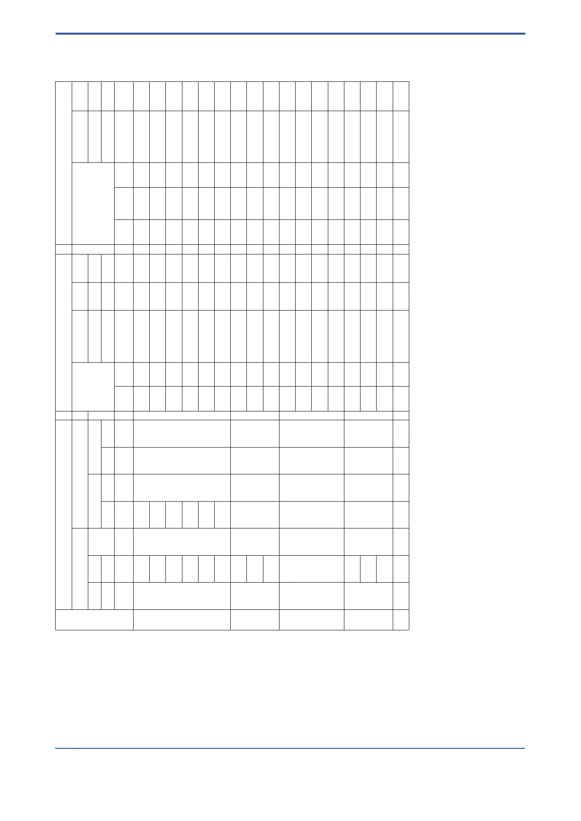
RAMC PROCESS CONNECTION- AND FLOW-TABLE FOR TUBES WITH PTFE LINING
Table 9-12
Pos.
Process connection Measuring range for water and liquids
Measuring range for air and gases
EN-Flange ASME-Flange
Max. Flow
Cone- Pressure
Max. Flow
Cone- Pressure
PN 16 PN40
L
(1)
150 lbs 300 lbs
Float- loss
a)
Visco Float- loss
a)
Code Code Code L
(1)
Code L
(1)
combination sity
b)
combination
D2 D4 mm A1 mm A2 mm m
3
/h
c)
gpm
d)
Code mbar mPa*s m
3
/h
c)
m
3
/h i.N.
e)
scfm
f)
Code mbar
2 - 250 250
¾ “
1“
250
0.1 0.45 51 A1 16 50 3.5 3.3 2 51 A1 20
0.16 0.7 52 A1 16 50 5 4.7 2.9 52 A1 20
DN15 ¾“ 0.25 1. 1 2 53 A1 16 50 8.5 8 5 53 A1 20
DN25 1“ 0.4 1. 8 54 A1 16 50 13 12 7. 5 54 A1 20
0.63 2.8 57 A1 16 50 20 18 11 57 A1 20
1 4.5 61 V1 18 50 34 32 20 61 V1 22
3 -
DN25
250
1 ¼ “
1½“
250
1 ¼ “
1½“
250
1. 6 7 62 A2 20 30 50 47 29 62 A2 25
DN40 2.5 11. 2 63 A2 20 10 85 80 50 63 A2 25
DN50 4 18 63 V2 22 50 - - - - -
4 -
DN50
DN65
DN80
250
2½“
3“
260
2½“
3“
270
4 18 64 A5 20 30 130 120 75 64 A5 25
6.3 28 67 A5 20 30 200 180 115 67 A5 25
10 45 71 A5 20 5 350 330 200 71 A5 25
16 70 71 V5 22 10 - - - - -
5 DN100 250
3½“
4“
270
3½“
4“
270
16 70 72 V8 25 10 500 470 290 72 V8 27
DN80 25 110 73 V8 25 10 850 800 500 73 V8 27
40 180 74 V8 25 10 - - - - -
6
DN100 DN100
250
4“
270
4“
270
63 280 77 10 30 10 - - - - -
(1) L = Mounting length
a) Pressure loss at the oat with water or air.
b) As from this viscosity the specied precision is no more guaranteed.
c) Flow is referred to 20°C and 1 bar abs.
d) Flow in US Gallons per minute at 70°F.
e) Flow referred to 0°C and 1.013 bar abs at operation conditions of 20°C and 1,013 bar abs.
f) Flow in Standard cubic feet per minute referred to 60°F and 14,7 PSI at operation conditions of 70°F und 14,7 PSI abs.
For your special application please use the Rota Yokogawa Sizing-Program.
 Loading...