9
All Rights Reserved. Copyright © 2012, Yokogawa Electric Corporation
GS 04L51B01-01EN
Nov. 10, 2015-00
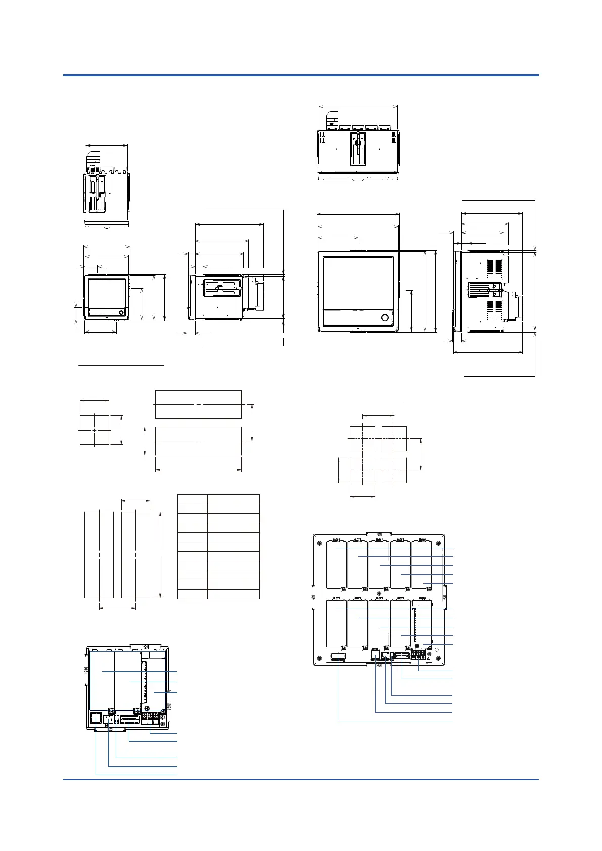
EXTERNAL DIMENSIONS AND
PANEL CUTOUT DIMENSIONS
GX10:
Panel cut dimensions
137
(5.39)
+2
0
137
(5.39)
(5.39)
+2
0
137
(5.39)
(6.89)
+2
0
175 MIN
175 MIN
L
+2
0
L
+2
0
L
+2
0
137
+2
0
2
3
4
5
6
7
8
9
10
n
282 (11.10)
426 (16.77)
570 (22.44)
714 (28.11)
858 (33.78)
1002 (39.45)
1146 (45.12)
1290 (50.79)
1434 (56.46)
(144×n)-6
Side-by-Side Mounting
(vertically, max. 3 units)
Side-by-Side Mounting
(horizontally)
Single-Unit
Mounting
Units
*1: with modules
*2: without moduels
Unless otherwise specified,
tolerance is ±3% (however,
tolerance is ±0.3 mm when
below 10 mm).
(*1)
(*2)
(Dimension before fitting attachment)
(Dimension after fitting attachment)
MAX
Thickness of attachment panel
26.6(1.05)
(0.90)
22.8
2(0.08) to 26(1.02)
157.7(6.21)
173.1(6.81)
224.4(8.83)
136.5
(5.37)
(0.30)
7.5
9.4(0.37)
(5.37)
151.5(5.96)
144(5.67)
40.9(1.61)
103.3(4.07)
103.3(4.07)
144(5.67)
151.5(5.96)
Rearview
Power supply terminal
I/O module (slot 1)
RS-422A/485 terminal (/C3)
or RS232 terminal (/C2)
USB port (/UH)
Ethernet port
FAIL/STATUS terminal (/FL)
I/O module (slot 2)
I/O module (slot 0)
GX20:
(14.17)
(14.21)
(11.06)
360 min.
361 min.
Panel cut dimensions
281
+2
0
281
0
Unit: mm (approx. inch)
Unless otherwise
specified, tolerance is
±3% (however,
tolerance is ±0.3 mm
when below 10 mm).
*1: with modules
*2: without moduels
(*1)
(*2)
(Dimension after fitting attachment)
(Dimension before fitting attachment)
MAX
Thickness of attachment panel
7.5(0.30)
9.4(0.37)280.2(11.03)
247.4(9.74)
32.3(1.27)
219.2(8.63)
168.8(6.65)
152.6(6.01)
2(0.08) to 26(1.02)
(1.11)
28.2
295.2(11.62)
288(11.34)
148(5.67)
295.2(11.62)
288(11.34)
144(5.67)
Rearview
Power supply terminal
RS-422A/485 terminal (/C3)
or RS232 terminal (/C2)
USB port (/UH)
Ethernet port
FAIL/STATUS terminal (/FL)
VGA output terminal (/D5)
I/O module (slot 0)
I/O module (slot 1)
I/O module (slot 2)
I/O module (slot 3)
I/O module (slot 4)
I/O module (slot 5)
I/O module (slot 6)
I/O module (slot 7)
I/O module (slot 8)
I/O module (slot 9)
PrecautionstoBeTakenWhileWiring
Withascrewterminal,werecommendthatyouuseacrimp-on
lugwithaninsulationsleeve(M4forpowersupplywiring,M3for
signal wiring).
Recommended signal wiring crimp-on lug
N1.25-MS3(JSTMfg.Co.,Ltd.)
 Loading...
