10-6 IM 760401-01E
Data Section
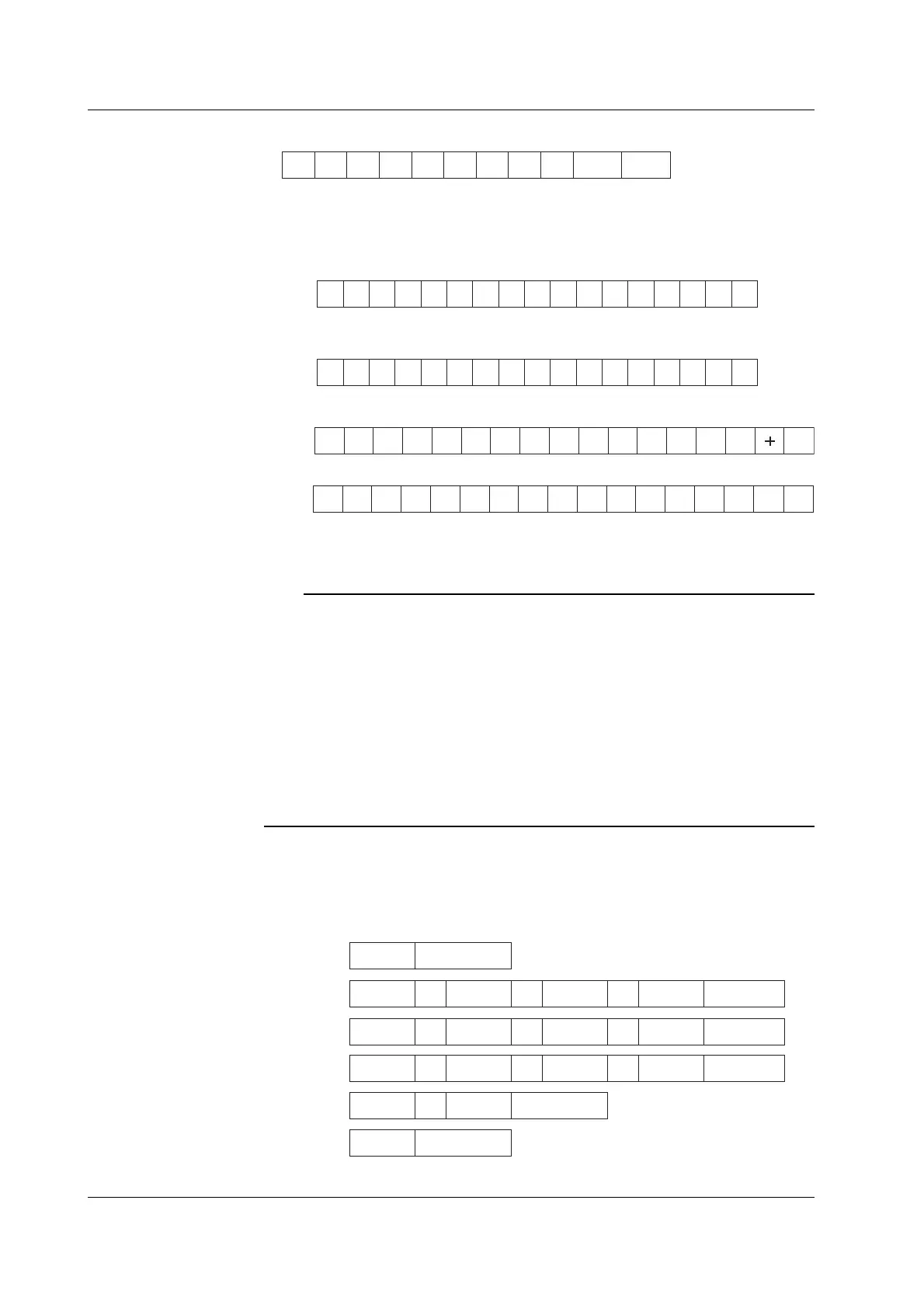
d1 d2 d3 d4 d5 d6 d7 d8 d9 d10 d11
d1: polarity; _ (space) or – (minus)
d2 to d8: mantissa, floating-point number of the maximum six digits
d9 to d11: exponent; E–3 → m, E+0, E+3 → k, E+6 → M
• Data state in case of an overrange (“oL” is being displayed)
h1 h2 h3 h4 I _ _ 9 9 9 9 9 9 . E + 3
• Data state in case of a computation overflow
(“oF”, “PFErr”, “dEGEr”, “ErrLo”, “ErrHi” is being displayed)
h1 h2 h3 h4 O _ _ 8 8 8 8 8 8 . E + 0
• Data state in case of no data (when the display is - - - - -)
h1 h2 h3 h4 E _ _ 9 9 9 9 9 9 . E 3
• Elapsed time of integration
HMS __ _d1d2d3 d4 d5 d6 d7 d8 d9 d10 d11
d1 to d5: Hour d6: “:”
d7 to d8: Minute d9: “:”
d10 to d11: Second
Note
• When the frequency is set by either of the following methods, only one value is measured,
and that value will be output.
• by panel keys : by the FUNCTION key and ELEMENT key of display C (except WT210)
• by communication command: by the “DC” or “EC” command.
After setting the measurement object of frequency, even changing the display C to something
different than VHz or AHz will not result in changing the object of measurement of frequency.
When selecting the output items yourself and you set a frequency item which is not object of
measurement, “999999.E+03” (no data) will be output.
• The displayed values of V (voltage), A (current), W (active power), VA (apparent power), var
(reactive power), Vpk (voltage peak), and Apk (current peak) while the MAX hold function
(see section 4.8) is enabled will be the maximum values (MAX) that are held. The values
output via communications are also set to the maximum values (MAX) that are held.
Output Format when Self Selected
Up to 14 normal measured/computed data can be output simultaneously, and the user
is allowed to choose any output information type for those 14 data. Each output block
is of the following format.
ch.1 , ch.2 ch.3 ch.4 Terminator, ,
ch.5 , ch.6 ch.7 ch.8 Terminator,
,
ch.9 , ch.10 ch.11 ch.12 Terminator,
,
ch.13 , ch.14
Terminator
END Terminator
Line 1
Line 2
Line 3
Line 4
Line 5
Line 6
Data
number
Terminator
(The data number will only be output in case of recall)
10.4 Output Measured/Computed Data, Setup Parameters, and Error Codes

 Loading...


