3-17
IM 760401-01E
Before Starting Measurements
3
Connecting an external sensor enables measurements when the current of the object to
be measured exceeds 20 A (10 A if the crest factor is set to 6). The range of the
external sensor input of the WT210/WT230 comes in two types, one for 2.5, 5, and 10 V
(1.25/2.5/5 V if the crest factor is set to 6) and another for 50, 100, and 200 mV (25/50/
100 mV if the crest factor is set to 6). You can select either option.
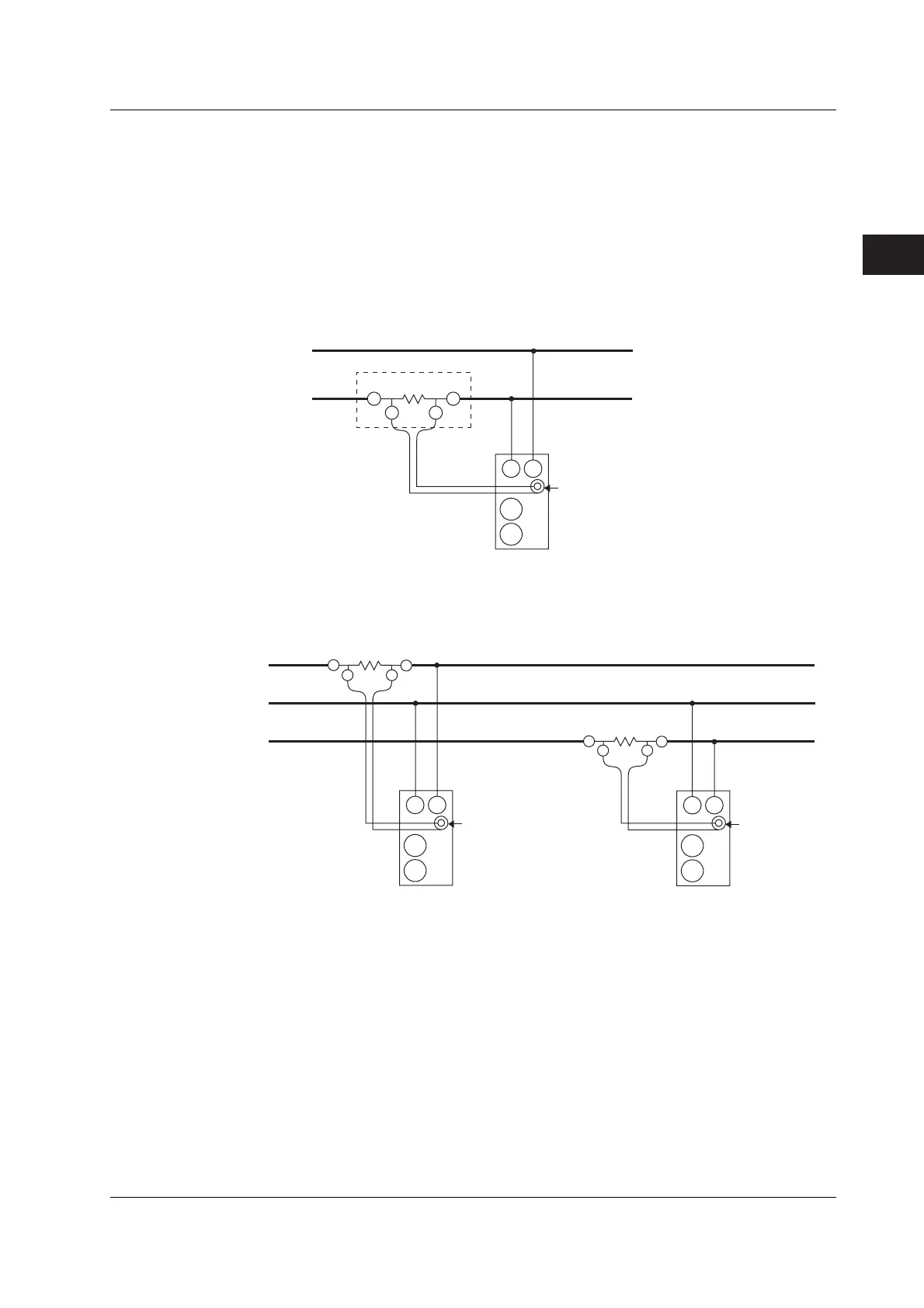
The following wiring examples are for connecting external shunts. When connecting a
clamp-type sensor, replace the shunt-type sensor with the clamp-type.
Wiring example of a single-phase, two-wire system (1P2W) when using an external
shunt ... Can be applied to models 760401, 760502, and 760503.
Source
Load
Connection
side
External shunt
OUT L OUT H
Input terminal
(Element)
External sensor input connector
(EXT)
C
±
±
V
Wiring example of a single-phase, three-wire system (1P3W) when using an external
shunt ... Can be applied to models 760502, and 760503.
Source Load
OUT L
OUT H
N
External sensor
input connector
(EXT)
Input terminal
(Element 1)
C
±
±
V
OUT LOUT H
External sensor
input connector
(EXT)
Input terminal
(Element 3)
C
±
±
V
3.9 Using an External Sensor to Wire the Circuit under Measurement

 Loading...


