3-18 IM 760401-01E
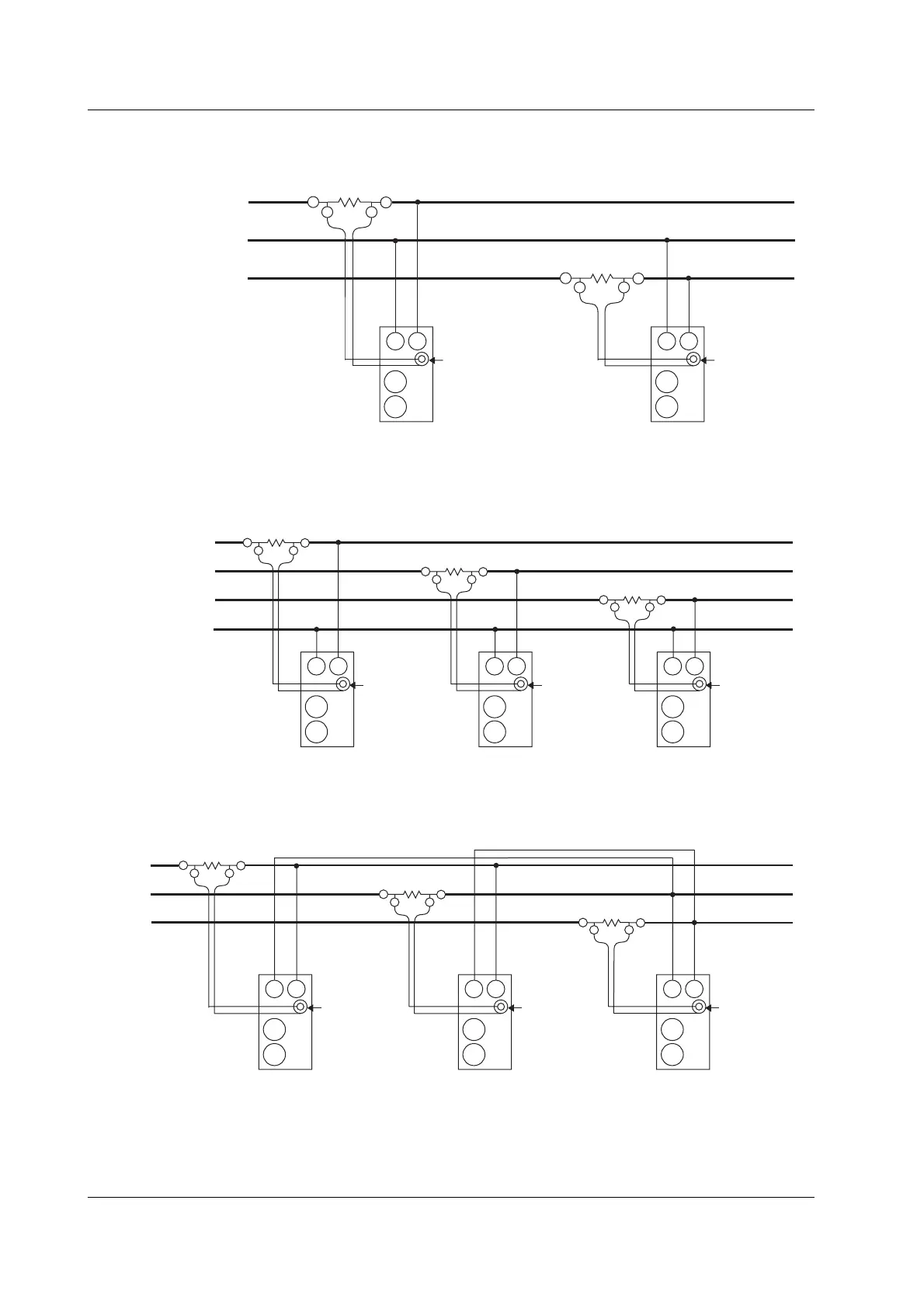
Wiring example of a three-phase, three-wire system (3P3W) when using an external
shunt ... Can be applied to models 760502, and 760503.
Source Load
OUT L
OUT H
U(R)
V(S)
W(T)
Input terminal
(Element 1)
Input terminal
(Element 3)
OUT L
OUT H
C
±
±
V
External sensor
input connector
(EXT)
External sensor
input connector
(EXT)
C
±
±
V
Wiring example of a three-phase, four-wire system (3P4W) when using an external
shunt ... Can be applied to model 760503.
Source Load
OUT LOUT H
U(R)
V(S)
W(T)
N
OUT L
OUT H
Input terminal
(Element 3)
Input terminal
(Element 1)
Input terminal
(Element 1)
OUT L
OUT H
External sensor
input connector
(EXT)
C
±
±
V
External sensor
input connector
(EXT)
C
±
±
V
External sensor
input connector
(EXT)
C
±
±
V
Wiring example of a three-voltage, three-current system (3V3A) when using an
external shunt ... Can be applied to model 760503.
Source Load
U(R)
V(S)
W(T)
OUT L
OUT H
OUT L
OUT H
Input terminal
(Element 3)
Input terminal
(Element 1)
Input terminal
(Element 2)
OUT L
OUT H
External sensor
input connector
(EXT)
C
±
±
V
External sensor
input connector
(EXT)
C
±
±
V
External sensor
input connector
(EXT)
C
±
±
V
3.9 Using an External Sensor to Wire the Circuit under Measurement

 Loading...


