5-3
IM 01C50C05-01EN
5.3 Cable Selection
5.3.1 Input signal Cable Selection
A dedicated cable is used for connection between the temperature sensor
and the temperature transmitter.
When a thermocouple is used as the temperature sensor, a compensation
wire which is appropriate for the type of thermocouple must be used (refer
to compensating cables for IEC584 thermocouples). When a resistance
temperature sensor (RTD) is used as the temperature sensor, 2-core/3-
core/4-core cable must be used (refer to resistance thermometer sensor
IEC751).
5.3.2 Output Signal Cable Selection
• Use cables of 0.13 to 2.08 mm
2
/ AWG26 to 14.
• For wiring in areas susceptible to electrical noise, use shielded wires.
• For wiring in high or low temperature areas, use wires or cables suitable
for such temperatures.
• For use in an atmosphere where harmful gases or liquids, oil, or solvents
are present, use wires or cables made of materials resistant to those
substances.
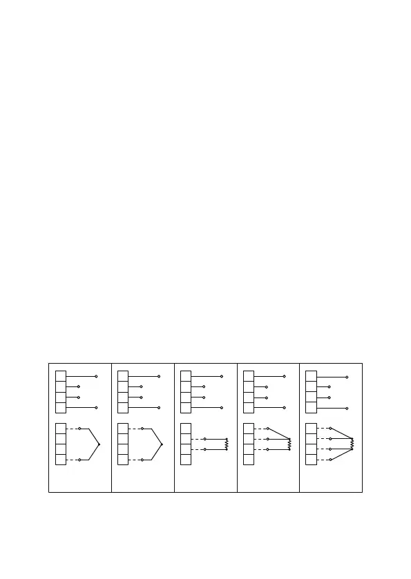
5.4 Cable and Terminal Connections
Wiring Diagram
11
12
13
14
41
42
43
44
11
12
13
14
41
42
43
44
T/Cs
Two-wire
RTDs or ohms
11
12
13
14
41
42
CJC
44
11
12
13
14
41
42
43
44
SUPPLY
(+)
(-)
SUPPLY
(+)
(-)
SUPPLY
(+)
(-)
SUPPLY
(+)
(-)
(+)
(-)
(A)
(B)
(A)
(B)
(B)
(A)
(B)
(B)
(A)
HART HART
HART HART
DC millivolts
11
12
13
14
41
42
43
44
SUPPLY
(+)
(-)
(+)
(-)
HART
Three-wire
RTDs or ohms
Four-wire
RTDs or ohms
F0504.ai
Figure 5.4 YTA70P Wiring Diagram

 Loading...


