A-6
IM 01C50C05-01EN
Appendix4.
CSA Installation drawing YTA70PQC01
YTA70PQC01 2014-08-14
1/1
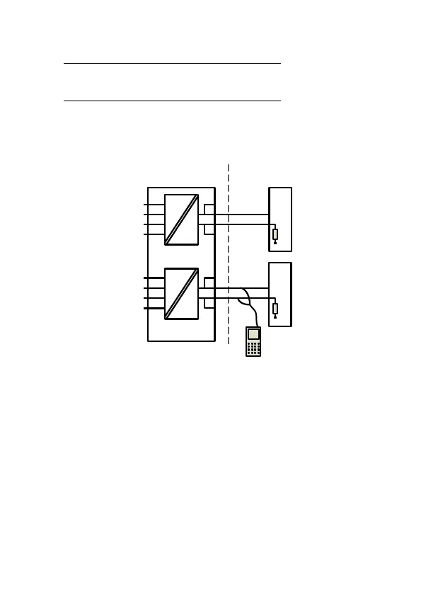
Installation drawing YTA70PQC01
13
12
44
43
42
41
+
-
Barrier
23
22
54
53
52
51
+
-
Barrier
CH2
CH1
21
24
14
11
Ex HART
Communicator
R
R
250 < R < 1100 ohm
Hazardous (Classified ) Location
IS, Class I, Division 1, Group A,B,C,D T6 or
Ex ia IIC Ga T6 or
Class I, Zone 0, AEx ia IIC Ga T6
Non Hazardous Location
Terminal:
41,42,43,44
Uo: 9.6 VDC
Io: 28 mA
Po: 67.2 mW
Lo: 35 mH
Co: 3.5μF
Terminal:
51,52,53,54
Uo: 9.6 VDC
Io: 28 mA
Po: 67.2 mW
Lo: 35 mH
Co: 3.5μF
Terminal:
11,12,13,14 and
21,22,23,24
Ui: 30 VDC
Ii: 120 mA
Pi: 0.84 W
Li: 10μH
Ci: 1.0nF
Co(Ca) > Σ(Ci+Ccable)
Lo(La) > Σ (Li+Lcable)
T6: -40 ≤ Ta ≤ 60ºC
Installation notes.
The Transmitter must be installed in a suitable enclosure to meet installation codes stipulated in The
Canadian Electrical Code (CEC) or for US in the National Electrical Code (NEC).
Channel 1 and Channel 2 are separate channels and therefore separate shielded cables
shall be used for each channel.
Substitution of components may impair intrinsic safety.

 Loading...


