5-1
IM 01C50C05-01EN
5. Wiring
5.1 Notes on Wiring
IMPORTANT
• Lay wiring as far away as possible from electrical noise sources such
as large transformers, motors and power supplies.
• To prevent electrical noise, the signal cable and the power cable must
not be housed in the same conduit.
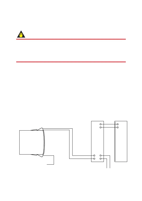
5.2 Loop Construction
The YTA70P is a two-wire temperature transmitter that uses the output
power supply wiring and signal wiring alternately.
The transmission loop requires DC power. Connect the transmitter with the
distributor as shown in Figure 5.1 or Figure 5.2.
For the transmission loop, the load resistance of the distributor or other
instrument to be installed in the loop and the lead wire must be within the
range shown in Figure 5.3.
F0501.ai
Input signal
(Thermocouples,
RTDs,DC millivolts,etc)
Output signal
Distributor
(Power supply unit) Receiver
+
–
Figure5.1 LoopConstruction(forGeneral-useType)

 Loading...


