A-1
IM 01C50C05-01EN
Appendix1.
ATEX Installation drawing YTA70PQA01
YTA70PQA01 2021-04-21
1/2
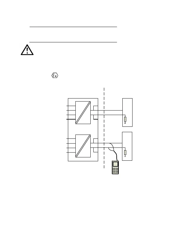
Installation drawing YTA70PQA01
For safe installation of theYTA70P-JA/V2S and YTA70P-JB/V2S the following must be observed.
The module shall only be Installed by qualified personnel who are familiar with the national and
international laws, directives and standards that apply to this area.
ATEX Certificate DEKRA 14 ATEX0106X
Marking
Standards EN IEC 60079-0:2018, EN60079-11:2012
Zone 0, 1, 2, 21, 22
II 1 G Ex ia IIC T6…T4 Ga
II 2 D Ex ia IIIC Db
41,42,43,44
Uo: 9.6 VDC
Io: 28 mA
Po: 67.2 mW
Lo: 35 mH
11,12,13,14 and
21,22,23,24
Ui: 30 VDC
Ii: 120 mA
Pi: 0.84 W
or Pi: 0.75 W
Li: 0 μH
51,52,53,54
Uo: 9.6 VDC
Io: 28 mA
Po: 67.2 mW
Lo: 35 mH
13
12
44
43
42
41
+
-
Barrier
23
22
54
53
52
51
+
-
Barrier
CH2
CH1
21
24
14
11
Ex HART
Communicator
R
R
250 < R < 1100 ohm

 Loading...


