6-2
IM 01C50C05-01EN
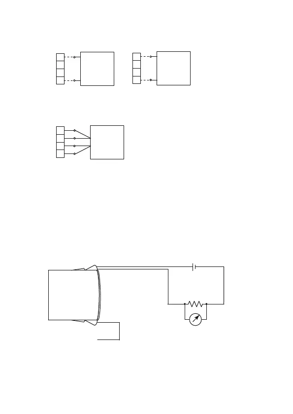
DC voltage generator
41
42
CJC
44
(+)
(-)
41
42
43
44
Variable resistor
(A)
(B)
(B)
(A)
DC voltage generator
41
42
43
44
(+)
(-)
T/Cs
DC millivolts
a. Example of wiring for thermocouples or DC millivolts input
b. Example of wiring for thermometer resistor 4-core type
F0601.ai
Figure 6.1 Example of Wiring for Trim sensor
2. Trim Analog Output
Fine current output adjustment is carried out with D/A trim. D/A trim is to be
carried out if the calibration digital meter does not exactly read 4.000 mA and
20.000 mA with an output signal of 0% and 100%.
• Procedure to call up the D/A trim display
Device setup → Diag/Service → Calibration → D/A trim
Input signal
(Thermocouples,
RTDs, DC millivolts,etc)
Output signal
Load resistance
Voltmeter
+
–
F0602.ai
Figure 6.2 Example of Wiring for analog trim

 Loading...


