No.
Model YTAxxx – F or – G
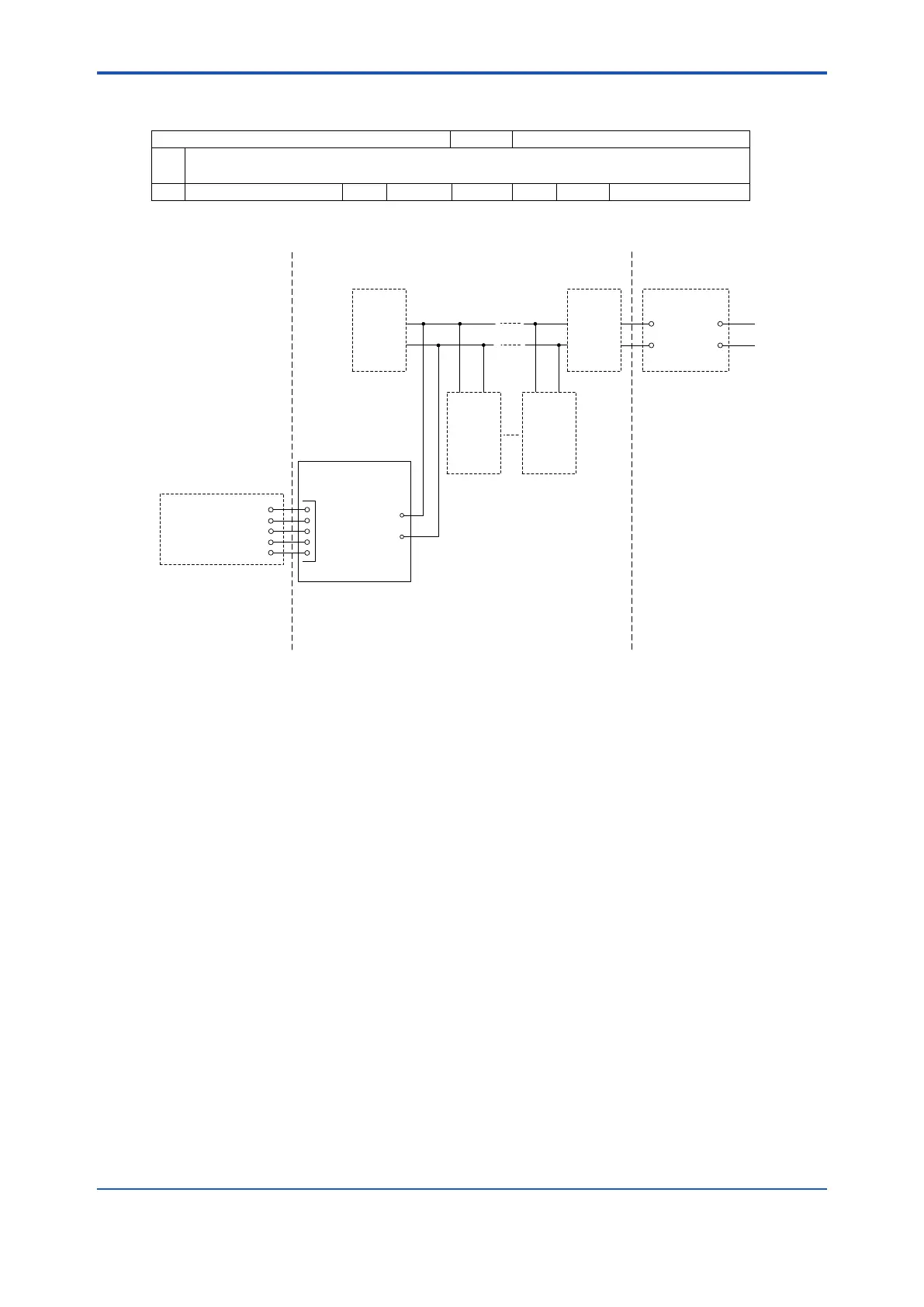
Supply/Output:
Ui = 32 V
Ci = 2.2 nF
Li = 0 mH
+
Model YTAxxx – F or – G
Temperature Transmitter
Associated Apparatus
−
+
−
+
−
1
2
3
4
5
Sensor Input:
Uo = 6.0 V
Io = 90 mA
Po = 135 mW
Co = 10 μF
Lo = 3.9 mH
Supply/OutputSensor Input
TerminatorTerminator
Field DeviceField Device
Intrinsically Safe Apparatus
or
Simple Apparatus
See Note 4
See Note 7
Class I, Division 2, Groups A, B, C, D
Class II, Division 2, Groups F, G
Class III, Division 1
Class I, Zone 2, Group IIC
Class I, Division 2, Groups A, B, C, D
Class II, Division 2, Groups F, G
Class III, Division 1
Class I, Zone 2, Group IIC
Temperature Class: T4
Hazardous (Classified) Location Unclassified LocationHazardous (Classified) Location

 Loading...


