<3. Installation>
3-3
IM 11M12G01-02EN 1sh Edition : Mar. 25, 2021-00
“11. Inspection and Maintenance”
the detector’s construction, especially the sensor assembly.
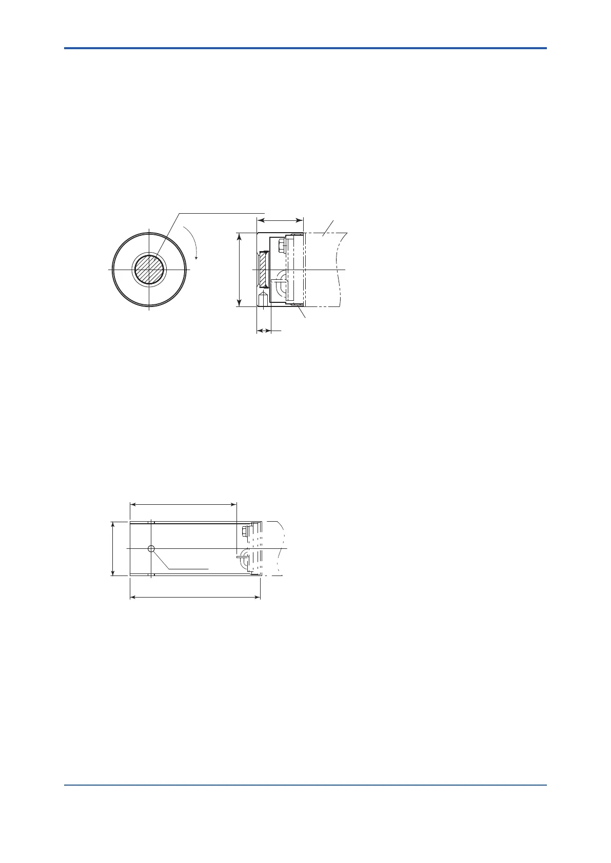
assembly clockwise. Put a hook pin wrench (K9471UX), Ø52 to Ø55 in diameter, into the
hole on the assembly to fasten or remove it.
Apply a heat-resistant coating (see Note 1) to the threads on the detector.
heat-resistant coating.
Note 1: As the detector is heated to 700°C, it is recommended to use heat-resistant coating on the threads to prevent seizing up.
Name of the heat-resistant coating material: NEVER SEEZ Nickel Special”.
Ø51
32
10
Carborundum filter (SiC)
Detector
Screw
Increasing of insertion length
F3-2E.ai
Attach the filter unit to the tip of
the detector by screwing it clockwise.
Figure 3.2 Installation of the dust lter
< Procedures for installing the dust guard protector (K9471UC)>
The ZR22G detector is shipped with the dust guard protector when the option code / F2 is
and water drops from lowering the detector performance is desired.
Screw the protector on the top of the detector so as to cover the top. When attaching or detaching
the protector, perform by hooking holes of its side with a hook pin wrench for Ø52 to Ø55 hole
(Pin diameter 4.5 mm: P/N K9741UX or the like) or by pass a screwdriver through the holes.
When re-attaching the protector after detaching it, apply the “NEVER SEEZ Nickel Special” to it.
4-Ø6
122
Ø50.8
100
Increasing of insertion length
F11-1.ai
Figure 3.3
<Detector with a probe protector (Model ZO21R-L-- *B for enhance forth>
The detector is used with a probe protector to support the probe (ZR22G) when the probe length
is 2.5 m or more and it is mounted horizontally.
the probe insertion hole.
(2) Make sure that the sensor assembly mounting screws (four bolts) at the tip of the detector
are not loose.
(3) Mount the detector so that the reference gas and calibration gas inlet faces downward.
 Loading...


