<4. Piping>
4-10
IM 11M12G01-02EN 1sh Edition : Mar. 25, 2021-00
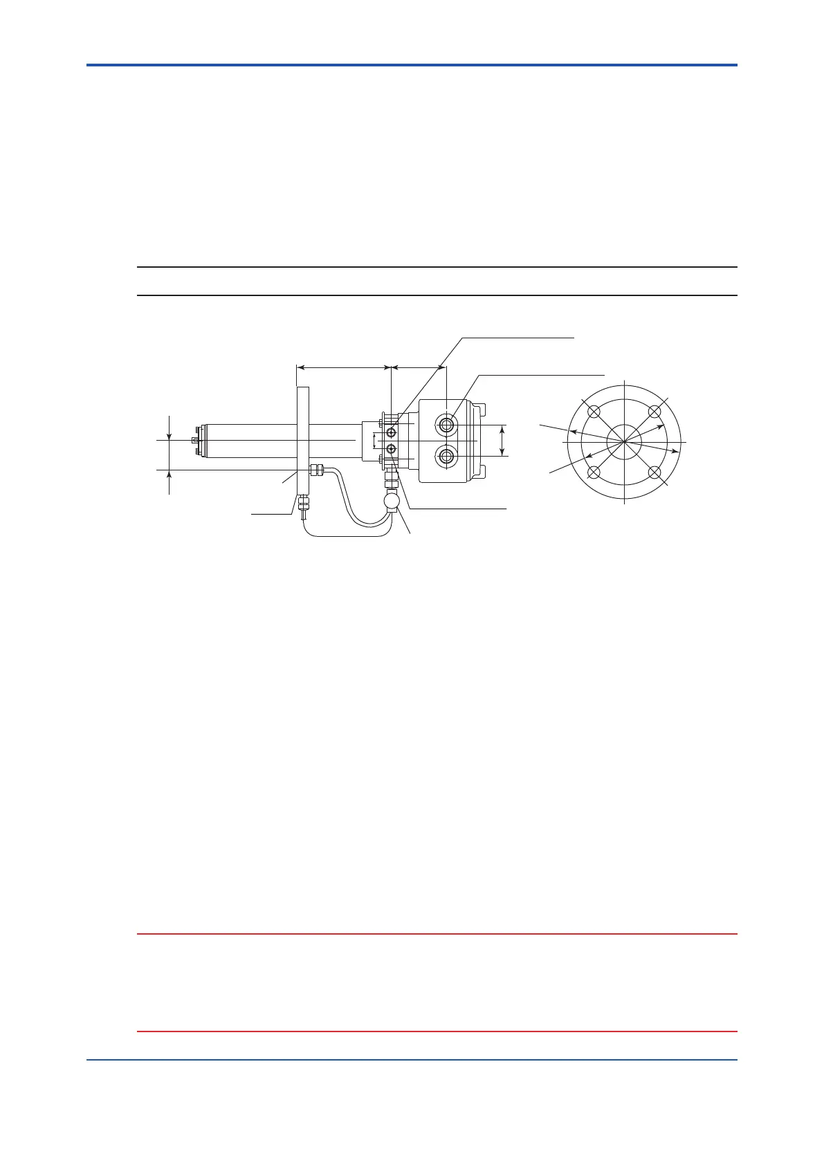
4.4 Piping for the Detector with Pressure
Compensation
The ZR22G----P Detector with Pressure Compensation may be used in System 2 and
System 3. However, it cannot use piping for high temperature probe adapter or blow back piping.
Use this detector whenever the furnace pressure exceeds 5 kPa (see Note). Even if the furnace
pressure is high, the detector can measure by adjusting pressure of the detector to the furnace
pressure using instrument air. The inside pressure of the probe will be kept the same as the
furnace pressure by feeding instrument air at higher pressure than that in the furnace.
NOTE
Sample gas pressure should not vary rapidly and widely.
*1
*1
*1
*1
Flange
156 87
Rc1/4 or 1/4NPT
Calibration gas inlet
25
48
Reference gas outlet
Flange
PIPING
PIPING
Stop Valve
Rc1/4 or 1/4NPT
Reference gas inlet
2-G1/2, 2-1/2NPT etc.
Cable connection port
*1 Dimensions may vary depending on the detector type. Refer to Section 2.2
Ensure that the flange gasket does not block the reference gas outlet.
Where necessary, make a notch on the flange
F4-12E.ai
*1
Figure 4.13 Detector with Pressure Compensation
Valve operation
(1)
For safety, stop the furnace that the detector is to be installed in. If furnace internal pressure
is high, this is especially dangerous.
(2)
gas outlet.
(3)
(4) Set the instrument air pressure higher than furnace internal pressure.
(5)
Completely open the stop valve in front of the reference gas outlet and, after turning on instrument air
(6)
(7)
CAUTION
entering the detector and damaging the zirconia cell.
• Connect the stop valve, which is at the calibration gas inlet, directly to the detector.
If there is piping between the detector and the valve, condensation may damage the
detector by rapid cooling when calibration gas is introduced.
 Loading...


