<5. Wiring>
5-9
IM 11M12G01-02EN 1sh Edition : Mar. 25, 2021-00
Figure 5.9 Connection of CJ compensation elements
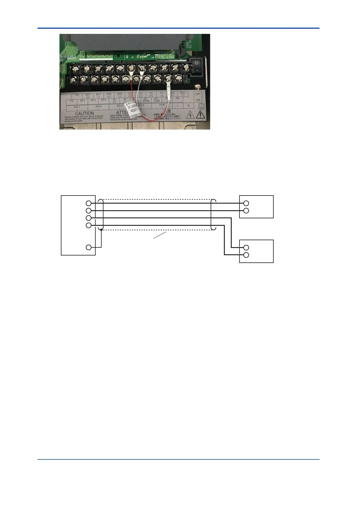
5.2.6 Wiring for Analog Output
This wiring is for transmitting 4 to 20 mA DC output signals to a device, e.g. recorder.
Shielded cable
Receiver 1
Receiver 2
ZR802G
Converter
1
2
1
2
AO-1(+)
AO-1(-)
AO-2(+)
AO-2(-)
FG
Figure 5.10 Wiring for analog output
Cable Specications
For this wiring, use a 2-core or a 4-core shielded cable.
Wiring Procedure
(1) M4 screws are used for the terminals of the converter. Each wire in the cable should be
terminated corresponding to crimp-on terminals. Ensure that the cable shield is connected
to the FG terminal of the converter.
(2) Be sure to connect “+” and “-” polarities correctly.
 Loading...


