<5. Wiring>
5-6
IM 11M12G01-02EN 1sh Edition : Mar. 25, 2021-00
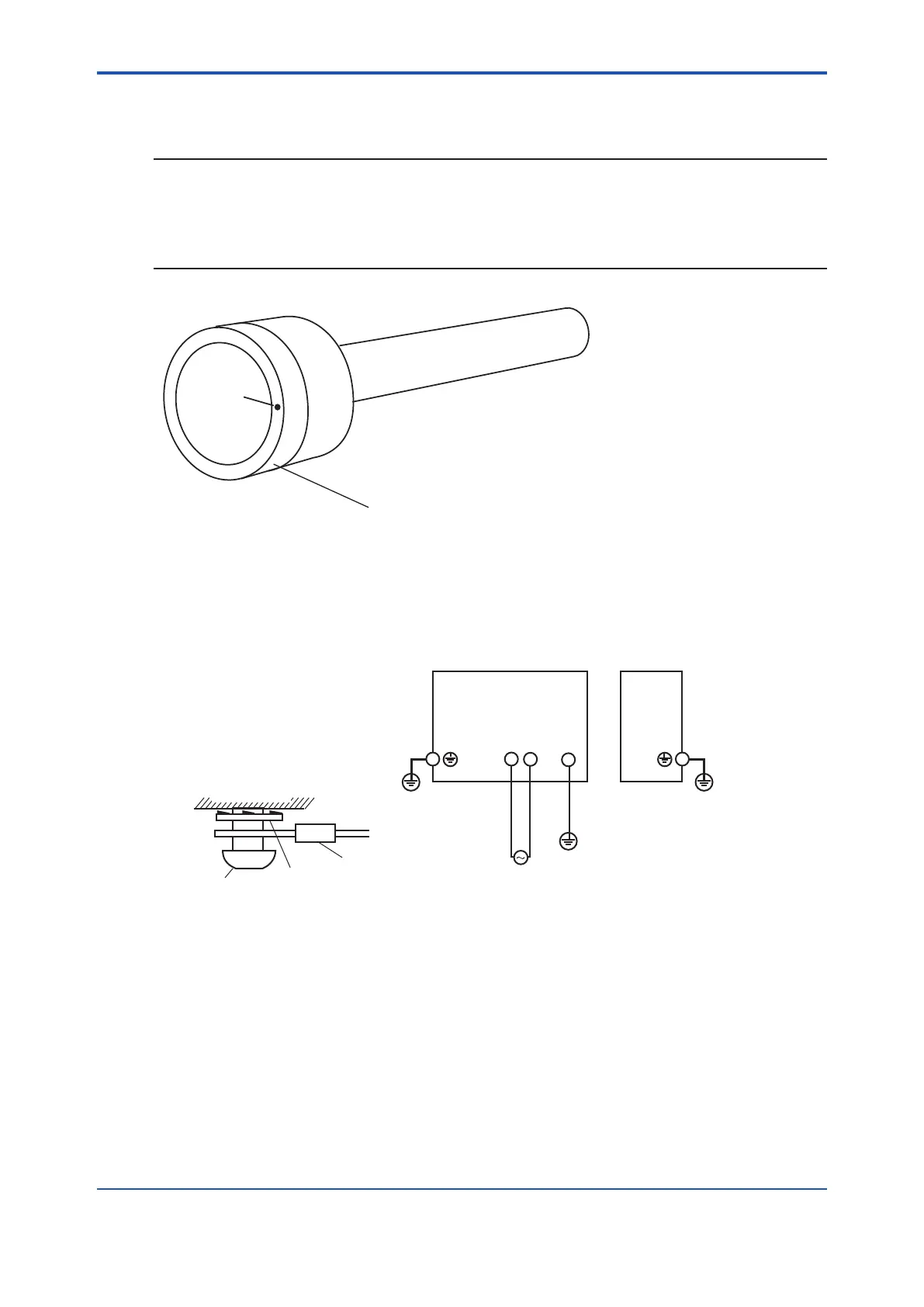
l Notice when closing the cover of the detector
NOTE
When opening and closing the cover, remove any sand particles or dust to avoid gouging
the thread.
• After screwing the cover in the detector body, secure it with the lock screw.
Lock screw
Detector cover
F5-8E.ai
Figure 5.5
5.2.3 Power and Grounding Wiring
This wiring supplies power to the converter and grounds the converter/detector.
L N G
100 to 240 V AC
50/60 Hz
Converter case
Grounding to the ground terminal
on the converter case
ZR802G
Converter
ZR22G
Detector
Ground
FG terminal
Lock washer
Crimp-on terminal of
the ground wire
Figure 5.6 Power and Grounding wiring
Power Wiring
Connect the power wiring to the L and N terminals of the converter. Proceed as follows:
(1) Use a 2-core or a 3-core cable.
(2) The size of converter terminal screw threads is M4. Each cable should be terminated
corresponding to crimp-on terminals.
Grounding Wiring
The ground wiring of the detector should be connected to the ground terminal of the detector
case. The ground wiring of the converter should be connected to either the ground terminal of the
The grounding terminals of the detector and the converter are of size M4. Proceed as follows:
 Loading...


