<5. Wiring>
5-8
IM 11M12G01-02EN 1sh Edition : Mar. 25, 2021-00
CELL(+)
CELL(+)
CELL(-)
CELL(-)
TC(+)
TC(+)
TC(-)
TC(-)
CJ(+)
CJ(+)
CJ(-)
CJ(-)
FG
Shielded cables
Shielded cables
ZR22G
Detector
ZR802G
Converter
CELL(+)
CELL(+)
CELL(-)
CELL(-)
TC(+)
TC(+)
TC(-)
TC(-)
CJ(+)
CJ(+)
CJ(-)
CJ(-)
FG
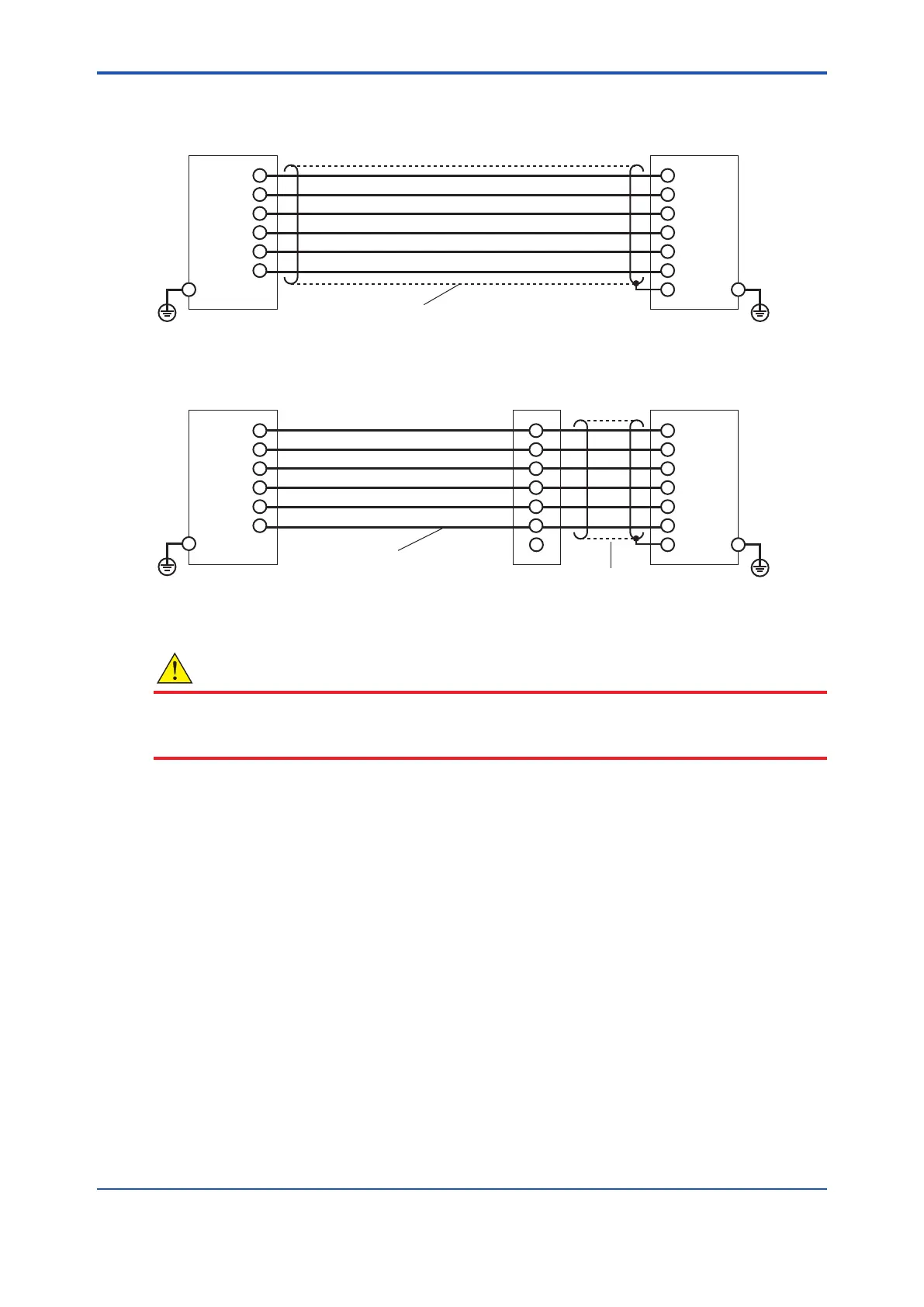
(2) Ambient temperature of the detector: exceeding 75°C
Heat-resistant wiring
Terminal box
(1) Ambient temperature of the detector: 75°C or less
ZR22G
Detector
ZR802G
Converter
Figure 5.8 Wiring for detector output
CAUTION
If shielded cables cannot be used between the detector and the terminal box, for example,
when heat-resistant wiring is used, locate the detector and the terminal box as close together as
possible.
Cable Specications
Basically, a cable (6-core) that withstand temperatures of at least 80°C is used for this wiring.
When the ambient temperature of the detector exceeds 75°C, install a terminal box, and connect
with the detector using six-piece 600 V silicon rubber insulated glass braided wires.
/CJ Option Specications
to the CJ (+) and CJ (-) terminals of the converter, and connecting the tip to the FG terminal (see
In addition, the cabling of the TCs is connected using compensating leads for TYPE K.
 Loading...


