<4. Piping>
4-8
IM 11M12G01-02EN 1sh Edition : Mar. 25, 2021-00
CHECK
OUT
ZERO GAS IN
AIR IN
Instrument air Approx.
1.5 l/min.
Flowmeter
Flowmeter
REF
OUT
*2 *2
EV1 EV2
Solenoid valve
EV1, EV2
F2-6-3E.ai
*2: Needle valve is supplied as accessory with flowmeter
*1 Shielded cable
Use a shielded cable for the signal cable, and connect the shield to the FG terminal of the transmitter.
*3 For zirconia type oxygen densitometers, 100 vol%N
2
gas cannot be used as zero gas. Normally, approximately 1 vol%O
2
(N
2
balanced) is used.
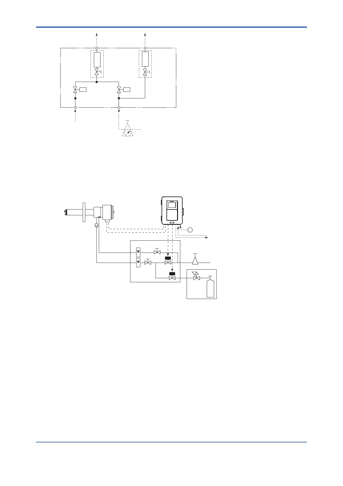
Figure 4.9 Piping inside in System 3
Instrument air
Pressure
reducing
valve
Air Set
Needle
valve
Flowmeter
Reference gas
Calibration gas
Check valve
~
Zero gas cylinder
ZR40H
Automatic Calibration Unit
ZR22G Separate type
Zirconia Oxygen/Humidity Analyzer, Detector
ZR802G Converter
Calibration gas
unit case
100 to 240 V AC
Contact input
Analog output, contact output
Digital output (HART)
Signal
(6-core shield cable)
Heater (2-core cable)
Figure 4.10 Piping for System 3
n Blow Back Piping
provides automatic blow back operation when the “ Blow back start “ command is entered to the
converter.
 Loading...


