JOHNSON CONTROLS
151
SECTION 4 - PRINTERS
FORM 160.78-O2
ISSUE DATE: 5/22/2017
4
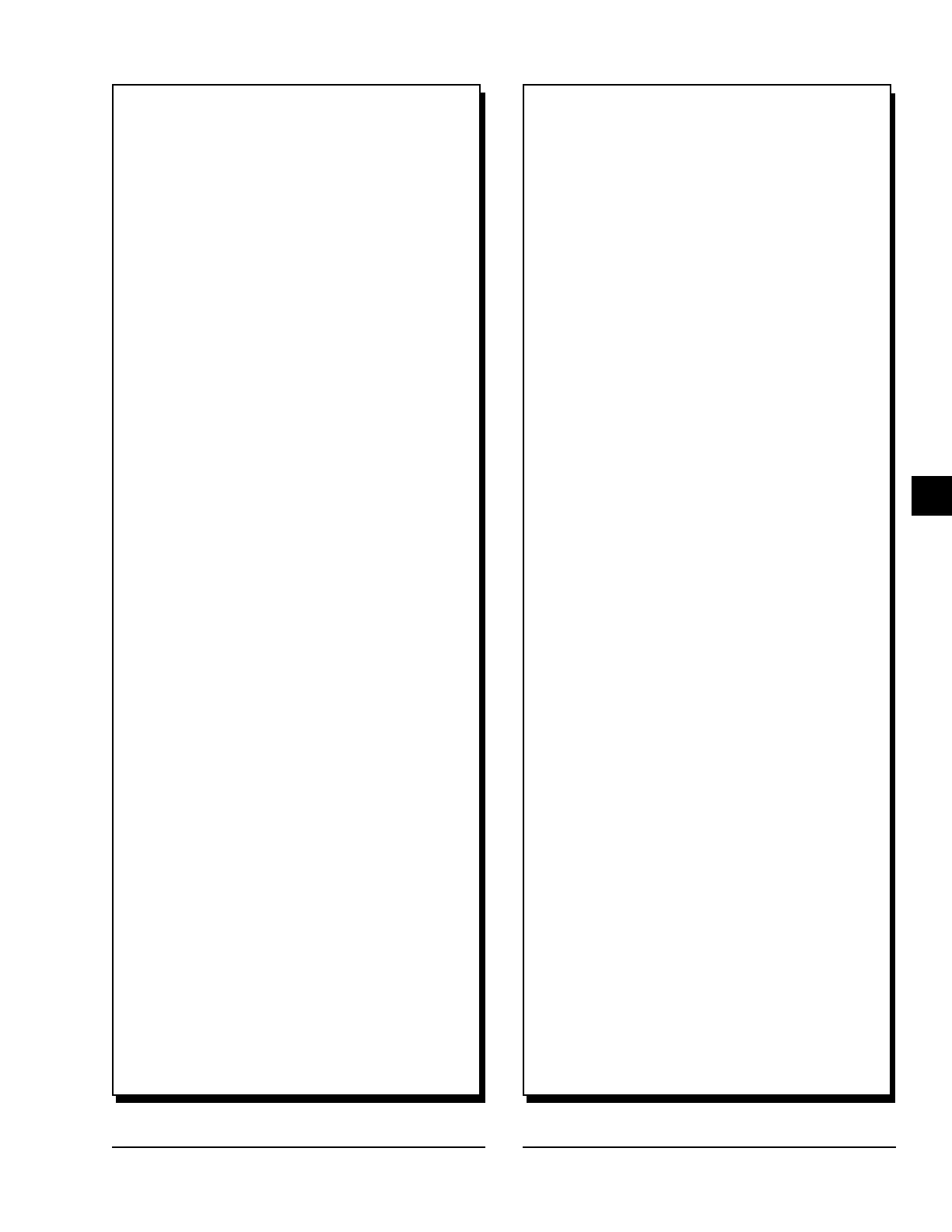
FIGURE 57 - SAMPLE PRINTOUT (STATUS) (CONT’D)
L1 Input Voltage (Peak) = 700 V
L2 Input Voltage (Peak) = 678 V
L3 Input Voltage (Peak) = 670 V
L1 Input Voltage (RMS) = 482 V
L2 Input Voltage (RMS) = 481 V
L3 Input Voltage (RMS) = 481 V
L1 Input Current (RMS) = 95 A
L2 Input Current (RMS) = 91 A
L3 Input Current (RMS) = 91 A
Phase A Output Voltage (RMS) = 259 V
Phase B Output Voltage (RMS) = 257 V
Phase C Output Voltage (RMS) = 258 V
Phase A Output Current (RMS) = 161 A
Phase B Output Current (RMS) = 161 A
Phase C Output Current (RMS) = 166 A
Phase A Rectier Baseplate Temperature = 108 ~F
Phase B Rectier Baseplate Temperature = 103 ~F
Phase C Rectier Baseplate Temperature = 98 ~F
Phase A Inverter Baseplate Temperature = 122 ~F
Phase B Inverter Baseplate Temperature = 117 ~F
Phase C Inverter Baseplate Temperature = 111 ~F
Internal Ambient Temperature 1 = 95 ~F
Internal Ambient Temperature 2 = 93 ~F
Test Mode = Disabled
Manual DC Bus = Disabled
Manual Cooling = Disabled
Motor Monitoring
-----------------------------------------------------
Motor Temperature 1 = 66 ~F
Motor Temperature 2 = 66 ~F
Motor Temperature 3 = 66 ~F
Motor Temperature 4 = 66 ~F
Motor Temperature 5 = 66 ~F
Motor Temperature 6 = 66 ~F
Average Winding Temperature = 66.0 ~F
Capacity Control
-----------------------------------------------------
Control State = Inactive
Load Limit = Inactive
VSD Frequency Command = 0.00 Hz
VSD Output Frequency = 0.00 Hz
VSD Control Mode = Auto
Active Anti-Surge Minimum Frequency = 0.00 Hz
Anti-Surge Minimum Frequency = 0.00 Hz
Anti-Surge Transient Offset = 0.00 Hz
VGD Command = 25.0% (Gas
Path B)
PRV Command = 25.0% (Gas
Path A)
VGD Position = 25.0% (Gas
Path B)
PRV Position = 25.0% (Gas
Path A)
VGD Control Mode = Auto (Gas
Path B)
PRV Control Mode = Auto (Gas
Path A)
Active Minimum PRV Position = 25.0% (Gas
Path A)
HGBP Command = 25.0 %
(only when HGBP enabled)
HGBP Control Mode = Auto
(only when HGBP enabled)
Head Pressure = 0.0 PSID
Evaporator Pressure (ltered) = 46.40 PSIG
Condenser Pressure (ltered) = 68.30 PSIG
Leaving Chilled Liquid Temperature (ltered) = 44.80 ~F
Magnetic Bearing Controller
-----------------------------------------------------
MBC Control Mode = Auto
MBC Command = Rotation
Delevitated Mode = Off
Levitated Mode = Off
Rotation Mode = On
MBC Shutdown = Off
Rotation Allowed = On
MBC Fault = Off
Motor Speed = 282 Hz
V13 Position = 10 ~m
W13 Position = 10 ~m
V24 Position = 8 ~m
W24 Position = 8 ~m
Z12 Position = 3 ~m
V1 = 2.164 A
V2 = 1.835 A
V3 = 0.533 A
V4 = 0.831 A
W1 = 1.913 A
W2 = 1.803 A
W3 = 0.800 A
W4 = 0.800 A
Z1 = 1.066 A
Z2 = 1.427 A
Rotor Elongation = 22 ~m
Motor Housing Temperature = 49.5 ~F
Landing Counter = 1
VW13 Vibration = 6 ~m
VW24 Vibration = 5 ~m
Z12 Vibration = 0 ~m
Z1 Temperature = 109 ~F
Z2 Temperature = 72 ~F
MBC Amplier Temp = 97 ~F
MBC Converter Temp = 111 ~F
MBC Operation Time = 40 Days
MBC Rotation Time = 39 Days
Number of Events = 100
Number of ESD Snapshots = 2
Number of Deceleration Snapshots = 2
AVR = Off
ABS = On
FIGURE 57 - SAMPLE PRINTOUT (STATUS) (CONT’D)