JOHNSON CONTROLS
155
SECTION 4 - PRINTERS
FORM 160.78-O2
ISSUE DATE: 5/22/2017
4
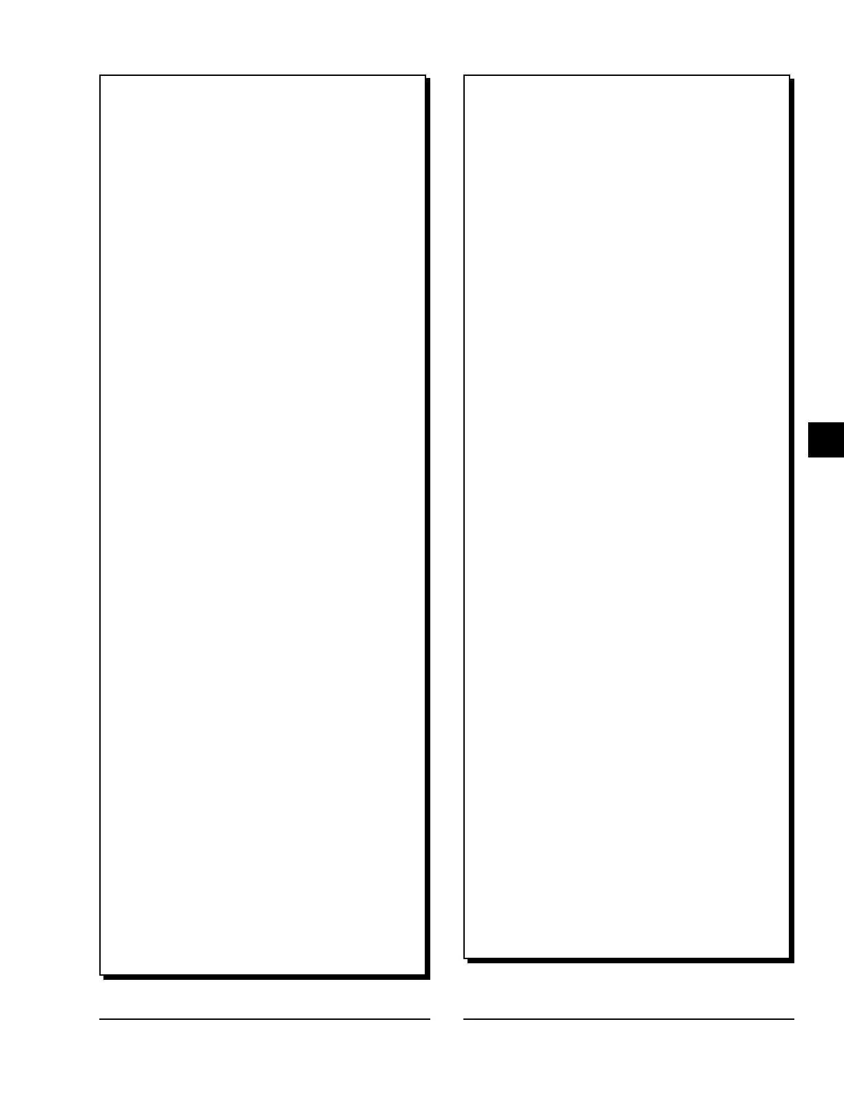
FIGURE 61 - SAMPLE PRINTOUT (HISTORY)
YORK HISTORY 1
SAMPLE CHILLER
YMC2-S1301AA
SCXM-100000
YMC2 Chiller ID 1
(c) 2010 Johnson Controls
Tue 07 Jun 2011 9:24:29 AM
SYSTEM RUN
VSD - PHASE A INPUT GATE DRIVER
Controls C.E38.16.00.012
Run Time 1 Days 23 Hr 3 Min 14 Sec
Operating Hours = 960 Hr
Number Of Starts = 307
Control Source = Analog
Run Permissive = True
Evaporator
------------------------------------------------------
Chilled Liquid Pump = Run
Chilled Liquid Flow Switch = Closed
Active LCHLT Setpoint = 42.0 ~F
Shutdown Temperature = 40.0 ~F
Leaving Chilled Liquid Temperature = 42.1 ~F
Entering Chilled Liquid Temperature = 45.2 ~F
Evaporator Pressure = 36.2 PSIG
Evaporator Saturation Temperature = 41.2 ~F
Evaporator Refrigerant Temperature = 41.2 ~F
Evaporator Small Temp Difference = 0.9 ~F
Condenser
------------------------------------------------------
Condenser Liquid Pump = Run
Condenser Liquid Flow Switch = Closed
Leaving Condenser Liquid Temperature = 82.7 ~F
Entering Condenser Liquid Temperature = 80.4 ~F
Condenser Pressure = 91.4 PSIG
Condenser Saturation Temperature = 82.8 ~F
Condenser Small Temp Difference = 0.1 ~F
Drop Leg Refrigerant Temp = 80.9 ~F
Subcooling Temperature = 1.9 ~F
Delta P = 55.2 PSID
Head Pressure Setpoint = 23.0 PSID
PID Control Mode =|Head
Pressure
Control Valve Command = 0.0 %
Compressor
------------------------------------------------------
Discharge Temperature = 107.2 ~F
Discharge Superheat = 24.4 ~F
Stop Bypass Valve = Off
PRV Opening = On (Gas
Path A)
PRV Closing = Off (Gas
Path A)
PRV Actuator Mode = Auto (Gas
Path A)
Surge
------------------------------------------------------
Surge Count = 0
Delta P / P = 1.52
Surge Window Time = 3 Min
Surge Window Count = 0
Refrigerant Level Control
-----------------------------------------------------
Refrigerant Level = 51.0 %
Active Level Setpoint = 50.0 %
Level Control State = Zone 1
Level Control Valve Command = 7.9 %
Variable Geometry Diffuser
-----------------------------------------------------
Active Stall Voltage = 0.29 V
Active Stall Voltage Type = Standard
Active High Limit = 0.53 V
Active Low Limit = 0.48 V
Mach Number = 1.24
VGD Opening = On
VGD Closing = Off
VGD Position = 25.0 %
(Gas Path
A)
Maximum VGD Position = 25.0 %
(Gas Path
A)
VGD Actuator Mode = Auto
VGD Control State = Probing
Time Remaining = 0 Sec
VGD Count = 132
VGD Time = 0 Days 3
Hr 37 Min 19 Sec
Discharge Pressure = 46.3 PSIG
Variable Speed Drive
-----------------------------------------------------
VSD Inverter =
D.H044.04.01.02.A01
VSD Rectier =
D.H044.03.01.02.A01
Motor Run = On
VSD Fault = On
Input % Full Load Amps = 30.8 %
VSD Output Voltage = 258 V
VSD Frequency Command = 282.82 Hz
VSD Output Frequency = 282.81 Hz
Max Chiller Frequency = 345.40 Hz
Input Power = 70 kW
Input kW Hours = 44456 kWh
L1 Voltage Total Harmonic Distortion = 9.0 %
L2 Voltage Total Harmonic Distortion = 5.0 %
L3 Voltage Total Harmonic Distortion = 5.0 %
L1 Input Current Total Demand Distortion = 8.0 %
L2 Input Current Total Demand Distortion = 6.0 %
L3 Input Current Total Demand Distortion = 7.0 %
Total Input KVA = 79 kVA
Total Power Factor = 0.89
Motor % Full Load Amps = 32.8 %
VSD Command = Run
VSD Control State = Run
FIGURE 61 - SAMPLE PRINTOUT (HISTORY)
(CONT'D)