Stereo microscope OPERATION
Stemi 305 Setting reflected-light illumination ZEISS
01/2015 435063-7044-001 29
4.2.2 Spot illuminator
• Push spot illuminator in the guide to the re-
quired height (Fig. 21/2).
In the lower positions, an oblique light
effect is created to produce cast sha-
dows for enhancing surface structures.
• Set the angle (Fig. 21/1) via the pivot of the
spot illuminator so that the object is optimally
illuminated.
• Set size and brightness of the spot by axially
shifting the focusing unit (Fig. 21/3)
(illumination zoom).
For switching the illumination intensity
ON and OFF and adjusting the
illumination intensity refer to Section
4.2.1, page 28.
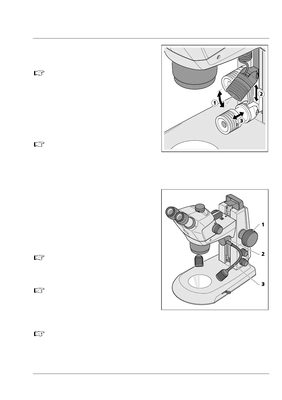
4.2.3 Double spot illuminator
• Move the microscope body to its uppermost
position via the focusing knob (Fig. 22/1). Push
double spot illuminator (Fig. 22/2) to the
required level within the guide.
• Bend the two goose necks (Fig. 22/3) to adjust
the spots so that the specimen is optimally
illuminated.
For switching the illumination intensity
ON and OFF and adjusting the
illumination intensity refer to Section
4.2.1, page 28.
Here again, an oblique light effect can
be produced in the lower positions with
the goose neck set horizontally.
The spot illuminator and the double spot illuminator have a thread M24 for placing
polarization filters in front. The appropriate analyzer is screw-fastened in the M52x1.0 thread
of the microscope body (Fig. 7/4).
By turning the spot polarizers, overexposure reflexes on the specimen can be reduced.
Fig. 21 Setting the spot illuminator
Fig. 22 Double spot illuminator