APPENDIX Stereo microscope
ZEISS List of illustrations Stemi 305
42 435063-7044-001 01/2015
6.3 List of illustrations
Fig. 1 Warning and information labels on the device................................................................... 11
Fig. 2 Warning labels and apertures for LED radiation .................................................................. 11
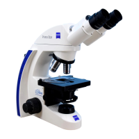
Fig. 3 Microscope system Stemi 305 ............................................................................................ 13
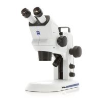
Fig. 4 Stemi 305 EDU microscope set .......................................................................................... 14
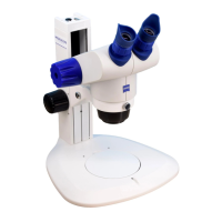
Fig. 5 Stemi 305 LAB microscope set ........................................................................................... 14
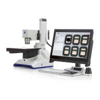
Fig. 6 Stemi 305 MAT microscope set ......................................................................................... 14
Fig. 7 Interfaces on the Stemi 305 with stand K LED (schematic diagram) ..................................... 15
Fig. 8 Front optics, Stemi 305 (example) ...................................................................................... 15
Fig. 9 Removing caps .................................................................................................................. 21
Fig. 10 Installing the stereo microscope ......................................................................................... 22
Fig. 11 Setting the ease of motion of the focusing drive ................................................................ 22
Fig. 12 Mounting spot illuminator ................................................................................................. 23
Fig. 13 Mounting ring illuminator on microscope body .................................................................. 24
Fig. 14 Mounting ring illuminator to front optics 3 ........................................................................ 24
Fig. 15 Mounting external fiber-optic illumination ......................................................................... 25
Fig. 16 Inserting the eyepiece plate ............................................................................................... 25
Fig. 17 Connecting the stereo microscope ..................................................................................... 26
Fig. 18 Adjusting the stereo microscope ........................................................................................ 27
Fig. 19 Adjusting the eyepieces ..................................................................................................... 27
Fig. 20 Setting the vertical illuminator ........................................................................................... 28
Fig. 21 Setting the spot illuminator ............................................................................................... 29
Fig. 22 Double spot illuminator ..................................................................................................... 29
Fig. 23 Ring illuminator ................................................................................................................. 30
Fig. 24 Controller K LED ............................................................................................................... 31
Fig. 25 Transmitted-light module in stand K EDU .......................................................................... 32
Fig. 26 Transmitted-light unit in stand K LAB ................................................................................. 33
Fig. 27 Changing the power unit .................................................................................................. 35
Fig. 28 Opening the stand cover plate, stand K EDU ..................................................................... 36
Fig. 29 Opening the stand cover plate, stand K LAB ....................................................................... 37