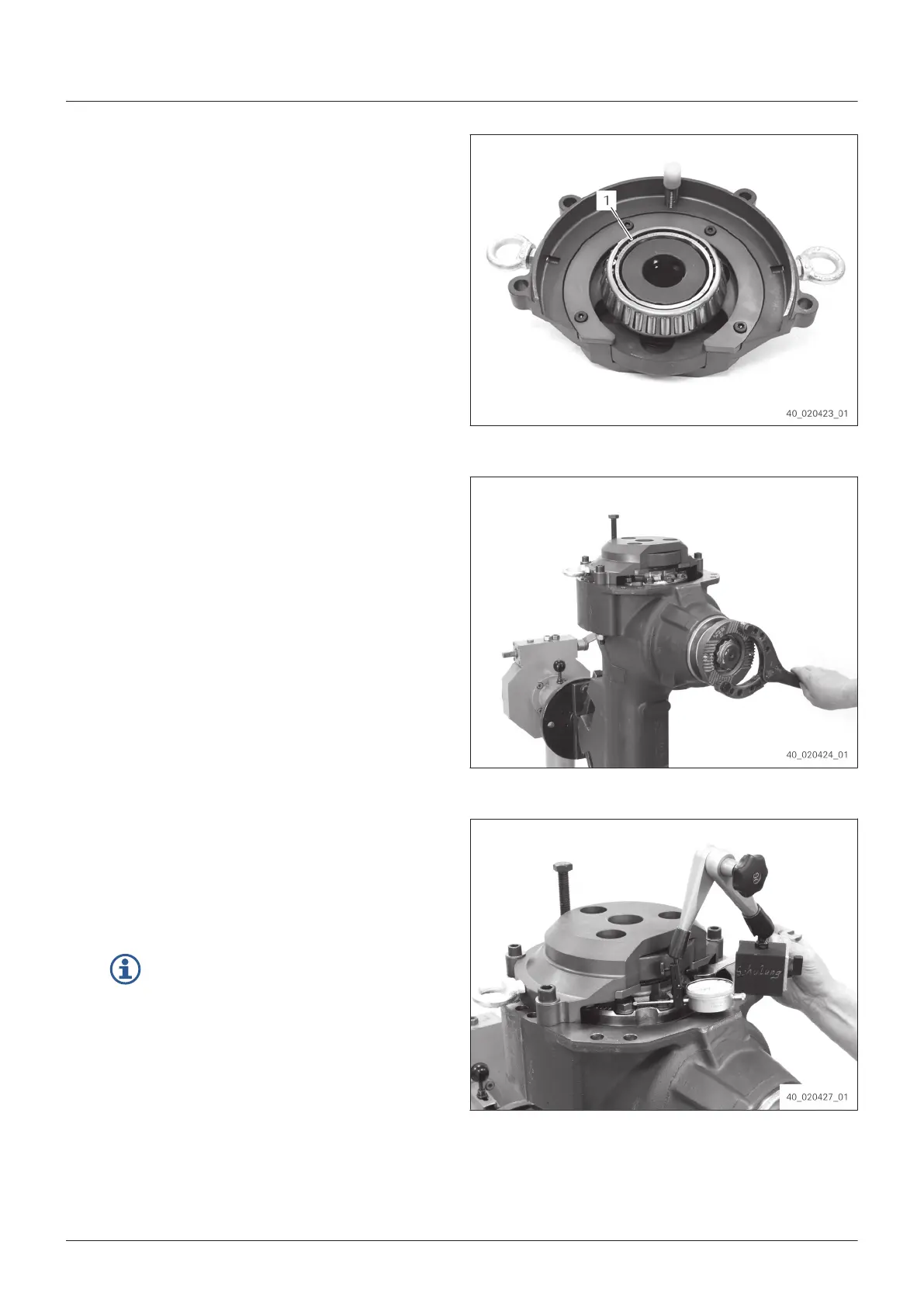
5. Slide bearing inner ring (1) onto
AA02.060.628 [T
est device].
Fig. 143
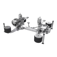
6. Put AA02.060.628 [Test device] onto the axle
housing.
7.
Install AA02.060.628 [Test device] evenly
with cylindrical screws until contact is
obtained.
8. Tighten cylindrical screws crosswise.
Tightening torque: 185 Nm
9. Turn pinion:
▪ Speed: 50 1/min
▪ Duration (always left and right): 15 s
Fig. 144
10. Place dial gauge at right-angled surface of a
he
xagon screw at the differential.
11. Backlash bevel gear set
e. g. 0.22 mm (±0.04 mm) Check
(see
Reassemble differential)
.
If the required backlash is not reached,
r
eplace the disk as specified below:
▪ In case of an insufficient backlash,
install a thicker shim.
▪ In case of an excessive backlash,
install a thinner disk.
Fig. 145
Assembly
82
EN 4472.751.001 - 2015-11