Information
Example of a possible tool list. The actual tool requirement depends on the respective motor being
used.
4.4 Mounting on the motor
The terminal box and terminal board must be removed to mount the frequency inverter on the motor.
The connections of the motor windings and the thermal protector are disconnected and connected to
the frequency inverter via an adapter.
(Connection diagram see Enclosure)
4.4.1 Procedure FSDM5/7.5/8.5
See the following drawing order 1. - 5.
1. Apply PU sealant “Bond + Seal” to the whole flange face of the motor terminal box (any uneven-
ness such as residue adhesive must be removed first to ensure that the adapter plate lies flat).
2. Fasten the adapter plate with the screws of the terminal box (2.5 Nm / 22.1 Lb In).
1 Holes for fastening adapter plate to flange of terminal box with the screws provided
2 Studs for fastening motor connection adapter with 2 x serrated locking nuts M4
3 Studs for fastening holder of the two PE clamps with 2 x serrated locking nuts M4
4 Studs for fastening cover terminal compartment with 5 x serrated locking nuts M5
5 Insert nuts for fastening frequency inverter with 4 x countersunk screws M5 x 20
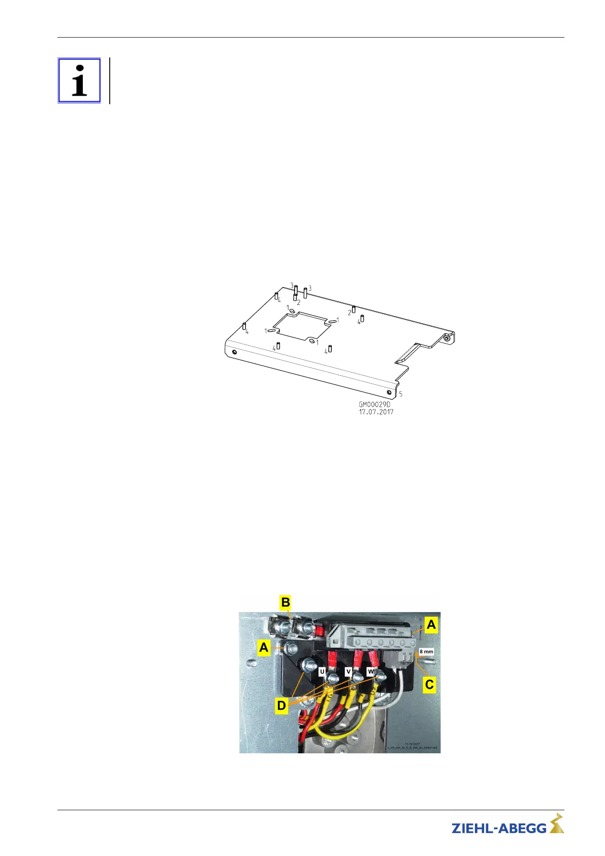
3. Fasten the motor connection adapter and make the electrical connection.
– A: Fasten the motor connection adapter with 2 x M4 serrated locking nuts (2.5 Nm / 22.1 Lb In)
– B: Fasten the holder and the two PE clamps with 2 x M4 serrated locking nuts and connect the
protective earth (2.5 Nm / 22.1 Lb In)
– C: Connect the “TB” or “TP” thermal protectors. Cut off any ring cable lugs in advance (required
stripping length 8 mm)
– D: Connect motor winding (2 Nm / 17.7 Lb In)
Attention!
Circuit type (Y or D) and settings of the frequency inverter must be compatible.
4. Fit the cover of the terminal compartment with five M4 serrated locking nuts (2.5 Nm / 22,1 Lb In).
5. Fasten the frequency inverter with four countersunk screws M5 x 20 (TORX T20) (2.5 Nm /
22.1 Lb In).
Operating Instructions PMIcontrol Basic-M – model series FSDM5...46 Mounting
L-BAL-E300-GB 1905 Index 001 Part.-No.
16/48

 Loading...