5.11 Relay outputs “K1”
An external fault indicator is available over the potential-free contact of the built-in relays (max. contact
rating
Technical data and connection diagram).
Function factory setting for “K1”:
•
For operation the relay is energized, connections “13” and “14” are bridged. For fault the relay is de-
energized (
Diagnostics / faults).
•
When switching off via enable (D1 = Digital In 1), the relay remains energized.
5.12 Status output “OC” (Open-Collector)
Depending on the operating state of the device, the output “OC” is switched to GND potential for a
certain number of pulses (output available depending on the model).
The status of the device can be displayed by this digitally coded signal.
Explanation of flash codes see Diagnostic / Status Out with flash code.
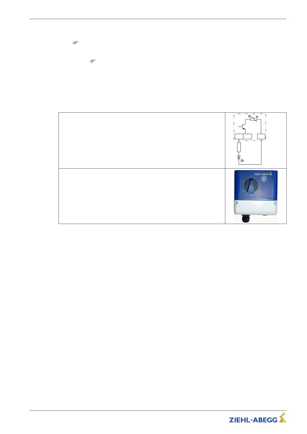
Wiring with external LED
With the output voltage “+10 V” a standard LED / low-power LED can be
controlled by using a pull-up resistor.
This lights when the output “Status Out OC” (OC = Open-Collector) is on GND
potential.
The details of which pull-up resistor needs to be used depend on the specification
on the LED that is used.
Display by LED in 5-step potentiometer type ZSG-5 (Part.-No. 349073)
In the case of the speed setting via the 5-step potentiometer, the status display
can be done via the integrated LED (for connection see operating instructions
ZSG-5).
5.13 Potential at control voltage connections
The connections for the control voltage (< 30 V) relate to the common GND potential (exception: relay
contacts are potential-free). There is a potential isolation between the connections for the control
voltage and the PE conductor. It must be ensured that the maximum external voltage at the con-
nections for the control voltage cannot exceed 30 V (between the “GND” and “PE” conductor
terminals). A connection to the PE conductor potential can be made if required; fit a bridge between
the “GND” terminal and the “PE” connection (terminal for shield).
Operating Instructions PMIcontrol Basic-M – model series FSDM5...46 Electrical installation
L-BAL-E300-GB 1905 Index 001 Part.-No.
34/48
 Loading...