5.6 Motor protection
Motor protection is possible by connecting thermostats “TB” (thermal contacts) or thermistors “TP”
(PTC).
The jumper on the device circuit board must be plugged according to the used thermal protector (see figure
terminal compartment).
Motor with thermistors “TP”
For motor with thermistors “TP” jumper plugged at bottom (factory setting).
A maximum of six single thermistors (DIN 44081 or DIN 44082) is permissible which are con-
nected in series.
When a connected thermostat or thermistor responds (interruption between the two terminals
“TB/TP”) the device switches off and does not switch back on.
Relais “K1” is de-energized, terminals “13” - “14” interrupted. The signal lamp flashes in code
|
15
|
(see Diagnostics / Faults).
" Switch back on after the drive has cooled down, i.e. in case of a connection between the terminals
“TB/TP”, by switching the line voltage off and back on.
5.7 Analog input “E1” for setting fan speed
The device has an analog input for setting the fan speed. Connection “E1” / “GND” (Analog In 1).
The internal jumper “E1.1” is factory set in the position for a 0...10 V or PWM speed setting signal.
For a 0...20 mA signal the plug “E1.1” must be replugged.
Danger due to electric current
•
Do not replug the jumper under voltage, observe the safety instructions!
•
Make sure the signal has the correct polarity!
•
Never apply line voltage to analog inputs!
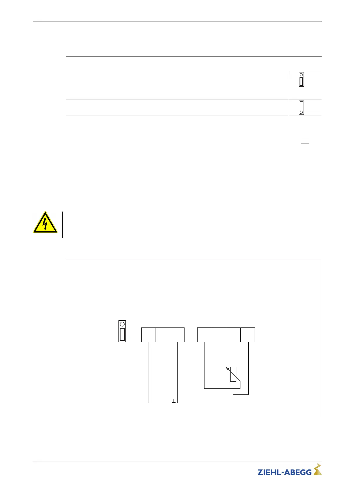
Possibilities for speed setting
0...10 V (factory setting)
Control via external setting signal 0...10 V
or
Speed setting by external potenziometer (10 kΩ) at terminals “+10 V” and “GND” pick of-off at terminal “E1”.
 Loading...