Second electrical connector - pin diagram (with cable coming from the body)
Body on neutral gear, information for the lifter (+)
Signal informing about lack of lifter (+) safety distance correct in the case of open systems,
from the side of the footboard (+)
Safety distance correct in the case of open systems, from the side of the step
Compaction stop/compaction to prevent collision/tank (+ = stop)
CAN bus termination (resistance to pin 15, 120 Ohm)
EMERGENCY STOP circuit 1 (connected to 9)
EMERGENCY STOP circuit 1 (connected to 8)
EMERGENCY STOP circuit 2 (connected to 11)
EMERGENCY STOP circuit 2 (connected to 10)
EMERGENCY STOP circuit check O.K. (+)
Automatic mode confirmation, system closed from ground level (+)
Move up, lifter is stopped, collision danger (+)
CAN bus termination (resistance to pin 7, 120 Ohm)
Automatic mode confirmation, system closed from ground level (+)
Total current consumption for electrical connectors = 8 A
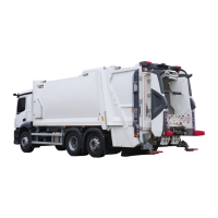
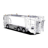
9.1.2 Dismantling of the mounting frame
Before proceeding with the planned collection of bulky waste, the mounting frame with the
lifter must be removed beforehand to facilitate loading.
Steps for dismantling the mounting frame with the lifter:
o Disconnect the 16-pol electrical and hydraulic connectors between the lifter and the
body. The electrical and hydraulic connectors remaining on the body must be
connected together to form closed circuits.
o Attach the mounting frame to the lifting device (lifting capacity at least 2 tonnes) using
the montage holders (Fig. 9.1)
o Unlock the spring bolt
o Insert the rod into the lift
o Raise the mounting frame until it unlocks