358 CHAPTER 19: ACL CONFIGURATION
[SW5500]acl number 2000
b Define the rules for packet which source IP is 10.1.1.1.
[SW5500-acl-basic-2000]rule 1 deny source 10.1.1.1 0 time-range 3Com
3 Activate ACL.
Activate the ACL 2000.
[SW5500-GigabitEthernet1/0/50]packet-filter inbound ip-group 2000
Link ACL Configuration
Example
Networking Requirements
Using Link ACL, filter the packet whose source MAC address is 00e0-fc01-0101 and
destination MAC address is 00e0-fc01-0303 during the time range 8:00 ~ 18:00
every day. The ACL is activated on GigabitEthernet1/0/50.
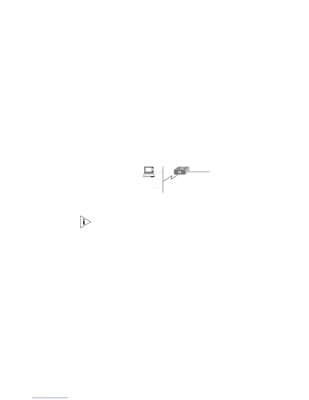
Networking Diagram
Figure 90 Access Control Configuration Example
Configuration Procedure
In the following configurations, only the commands related to ACL configurations are
listed.
1 Define the time range
Define time range from 8:00 to 18:00.
[SW5500]time-range 3Com 8:00 to 18:00 daily
2 Define the ACL for the packet whose source MAC address is 00e0-fc01-0101 and
destination MAC address is 00e0-fc01-0303.
a Enter the numbered link ACL, number as 4000.
[SW5500]acl number 4000
b Define the rules for the packet whose source MAC address is 00e0-fc01-0101 and
destination MAC address is 00e0-fc01-0303.
[SW5500-acl-ethernetframe-4000]rule 1 deny source 00e0-fc01-0101
ffff-ffff-ffff source 00e0-fc01-0303 ffff-ffff-ffff time-range 3Com
3 Activate ACL.
Activate the ACL 4000 .
[SW5500-GigabitEthernet1/0/50]packet-filter inbound link-group 4000
Switch
#1
connect to Router