NTP Overview 493
■ Record for an application when a user logs in to a system, a file is modified, or
Basic Operating Principle of NTP
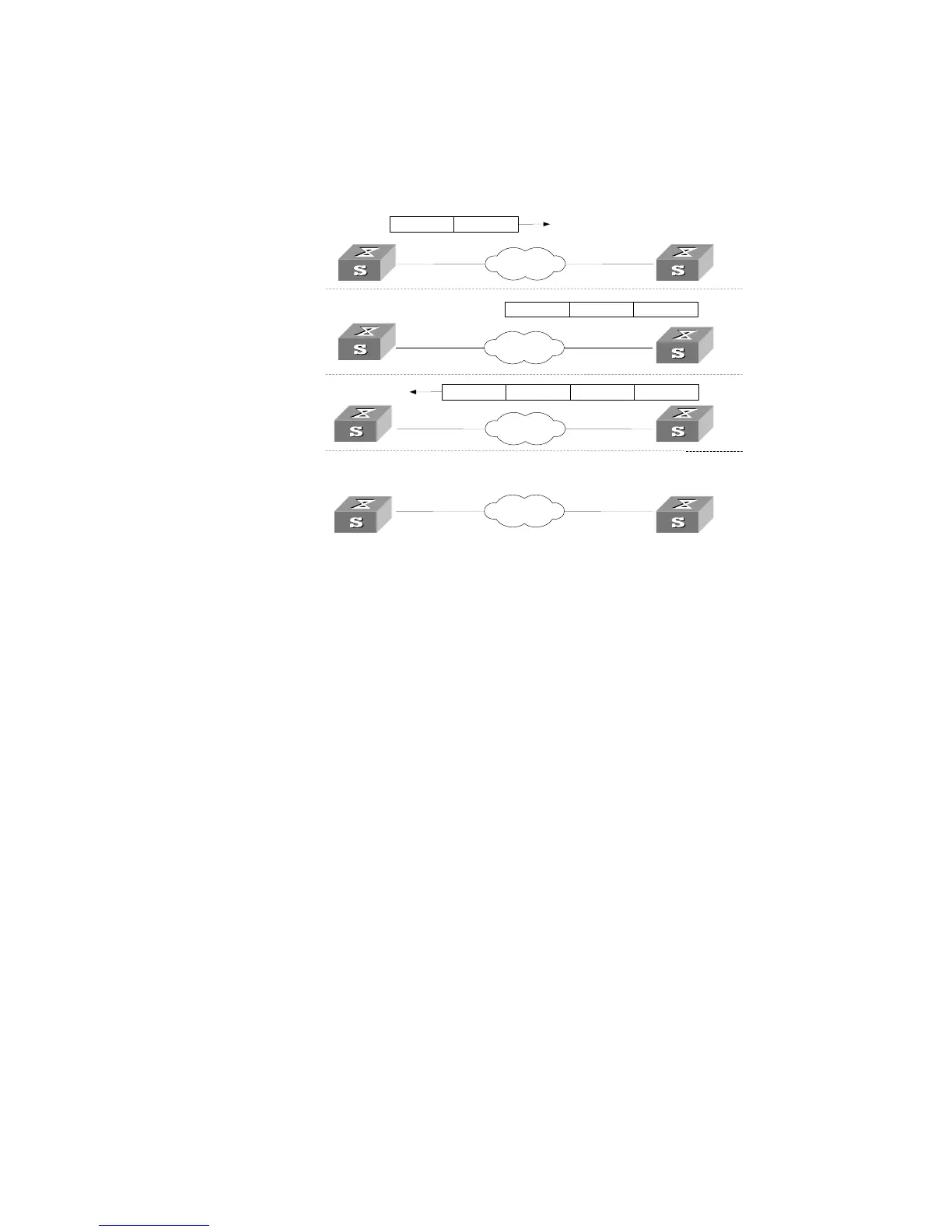
Figure 131 illustrates the basic operating principle of NTP:
Figure 131 Basic Operating Principle of NTP
In Figure 131, Switch A and Switch B are connected using the Ethernet port. They
have independent system clocks. Before implementing automatic clock
synchronization on both Switches, it is assume that:
■ The clock on Switch A is set to 10:00:00am, and that on B is set to 11:00:00am.
■ Switch B serves as an NTP time server. That is, Switch A synchronizes the local
clock with the clock of B.
■ It takes 1 second to transmit a data packet from either A or B to the opposite end.
The system clocks are synchronized as follows:
■ Switch A sends an NTP packet to Switch B. The packet carries the timestamp
10:00:00am (T
1
) that tells when it left Switch A.
■ When the NTP packet arrives at Switch B, Switch B adds a local timestamp
11:00:01am (T
2
) to it.
■ When the NTP packet leaves Switch B, Switch B adds another local timestamp
11:00:02am (T
3
) to it.
■ When Switch A receives the acknowledgement packet, it adds a new timestamp
10:00:03am (T
4
) to it.
Now Switch A collects enough information to calculate the following two important
parameters:
■ The delay for a round trip of an NTP packet travelling between the Switch A and B:
Delay= (T
4
-T
1
) - (T
3
-T
2
).
■ Offset of Switch A clock relative to Switch B clock: offset= ( (T
2
-T
1
) + (T
4
-T
3
) ) /2.
Network
Network
NTP消息包 10:00:00am
Network
Network
11:00:01am
NTP消息包 10:00:00am 11:00:01am 11:00:02am
NTP消息包 10:00:00am
NTP Packet received at 10:00:03
1.
2.
3.
4.
LS_A
LS_A
LS_A
LS_A
LS_B
LS_B
LS_B
LS_B












 To Next Page