500 CHAPTER 22: FILE SYSTEM MANAGEMENT
Networking Diagram
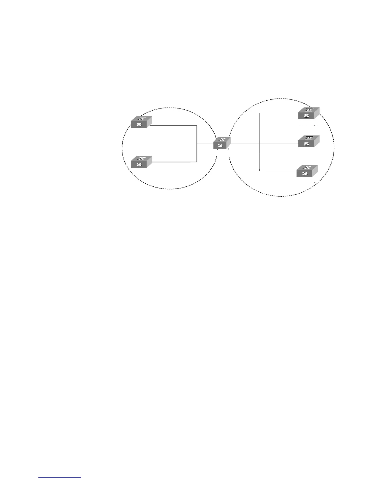
Figure 132 Typical NTP Configuration Networking Diagram
Configuration Procedure
Configure Switch 1:
1 Enter System View.
<switch1> system-view
2 Set the local clock as the NTP master clock at stratum 2.
[switch1]ntp-service refclock-master 2
Configure Switch 2:
1 Enter System View.
<switch2> system-view
2 Set SW5500 1 as the NTP server.
[switch2]ntp-service unicast-server 1.0.1.11
The above examples synchronized Switch 2 by Switch 1. Before the synchronization,
the Switch 2 is shown in the following status:
[switch2]display ntp-service status
clock status: unsynchronized
clock stratum: 16
reference clock ID: none
nominal frequency: 100.0000 Hz
actual frequency: 100.0000 Hz
clock precision: 2^17
clock offset: 0.0000 ms
root delay: 0.00 ms
root dispersion: 0.00 ms
peer dispersion: 0.00 ms
reference time: 00:00:00.000 UTC Jan 1 1900(00000000.00000000)
......
Vlan-interface2:
1.0.1.11
Quidway0
Quidway1
Quidway2
Quidway3
Quidway4
Quidway5
Vlan-interface2:
1.0.1.12
Vlan-interface2:
3.0.1.31
Vlan-interface2:
3.0.1.32
Vlan-interface2:
3.0.1.33
1.0.1.2 3.0.1.2
Switch 1
Switch 2
Switch 3
Switch 4
Switch 0
Switch 5