2
Feature Description
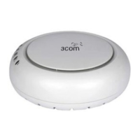
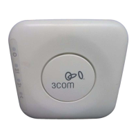
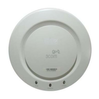
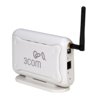
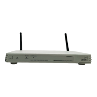
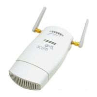
Ethernet Port
The Ethernet port provides a 10/100/1000 BASE-T Ethernet
connection to a switch. Use a suitable Category 5 cable with
straight-through wiring and standard RJ-45 connectors to
connect your AP to the network.
LEDs
The LEDs indicate power and activity. See
Checking the LED
Indicators for details.
Antenna Connectors
The AP has three built-in internal antennas. In addition, three
RSMA antenna connectors allow you to connect optional
external antennas.
Reset Button To reset the AP.
RJ-45 Console Port
Provides a serial interface to the AP for diagnostic use.
Default: 9600 baud rate, 8 data bits, no parity, one stop bit.
The default username and password for console login are
admin
and
password
(case sensitive) respectively.
Wall-Mounting
Bracket and
Table-Top Stand
The combined wall-mounting bracket and table-top stand
allows you to mount the unit on a wall or stand it on a table top.
Suspended Ceiling
Bracket
The suspended ceiling bracket (ceiling bracket and slider)
allows you to mount the unit on a suitably ceiling tile separator.
Safety Information
This equipment must be installed in compliance with local and national building codes,
regulatory restrictions, and FCC rules. For the safety of people and equipment, only
professional network personnel should install the AP.
: Warnings contain directions that you must follow for your personal
safety. Follow all directions carefully.
You must read the following safety information carefully before you install or remove the unit.
: Exceptional care must be taken during installation and removal of the unit.
: This unit operates under SELV (Safety Extra Low Voltage) conditions
according to IEC60950-1. The conditions are only maintained if the equipment to which
it is connected also operates under SELV conditions.